Load Data to Root-Level Input Ports
You can load data from a workspace to a root-level inport modeled using one of these blocks:
These blocks import data from the workspace based on the value of the Configuration Parameters > Data Import/Export > Input parameter.
Tip
To import many signals to root-level input ports, consider using the Root Inport Mapper tool. For more information, see Map Root Inport Signal Data.
You can also import data from a workspace using a From Workspace block. For details, see the From Workspace documentation and Load Input Data for Basic Test Cases.
Specify Input Data
You can specify input data manually, using the Input configuration parameter. To load many signals to root-level input ports, consider using the Root Inport Mapping tool, which automatically specifies in the Input parameter the data you map using the tool. For details, see Map Data Using Root Inport Mapper Tool.
Select the Configuration Parameters > Data Import/Export > Input parameter.
Note
The use of the Input configuration parameter is independent of the setting for the Format configuration parameter for saving logged data.
Enter an external input specification in the adjacent edit box and click Apply. For a list of the forms of data you can specify, see Forms of Input Data.
In the Input box, specify the signal input using one of these approaches:
Create data at run-time for each simulation time step using the input
u =
              UT(t)
for either a MATLAB® function (expressed as a string) or MATLAB expression.Specify the data directly, using one of the input data forms described in Forms of Input Data.
Comma-Separated List
If you specify Dataset data, specify only one
Dataset object for the Input parameter. Do not
include it in a comma-separated list.
Each variable or expression must evaluate to an appropriate object that corresponds to a specific root-level input port in the model. Each variable or expression in the list must evaluate to the appropriate object that corresponds to one of the root-level input ports of the model. The first item corresponds to the first root-level input port, the second to the second root-level input port, and so on. The dimensions for each data sample must match the dimensions of the data specified in the input block parameter.
For an Enable or Trigger block, the signal driving the enable or trigger port must be the last item in the comma-separated list. If you have both an enable and a trigger port, then specify:
The enable port as the next-to-last item in the list
The trigger port as the last item
Use an empty matrix to specify ground values for a port. For example, to load data for
input ports in1 and in3, and to use ground values
for port in2, enter the following in the Input
parameter:
in1, [], in3
Forms of Input Data
You can provide input data with the following formats:
Simulink.SimulationData.Dataset— Collection of logged data in MATLABtimeseriesformat. For more information, see Loading Dataset Data to Root-Level Inputs.MATLAB
timeseries— For more information, see:Simulink.SimulationData.DatasetRef— For more information, see Load Big Data for SimulationsMATLAB
timetable— For more information, see Loading MATLAB Timetable Data to Root-Level Inputs.Array — See Loading Data Arrays to Root-Level Inputs.
Simulink.SimulationData.Signal— For more information, see Load Data Logged in Another Simulation.matlab.io.datastore.SimulationDatastore— For more information, see Work with Big Data for Simulations.Structure — To simplify the specification of external input data, you can load data for a subset of root-level input port blocks. This approach avoids having to create data structures for the ports for which you want to use ground values. For information about ground values, see Initialize Signals and Discrete States. For more information about loading structure data, see Loading Data Structures to Root-Level Inputs.
Structure array containing data for all input ports.
Empty matrix — Use an empty matrix for ports for which you want to use ground values, without having to create data values.
Time expression — For more information, see Loading MATLAB Time Expressions to Root Inports.
Note
When you specify timetable data to load, the
timetable must contain data for only one signal.
For information about importing bus data, see Load Bus Data to Root-Level Input Ports.
Time Values for the Input Parameter
Time values that you specify in the Input parameter do not control the times the solver uses. Solvers have their own logic for propagating time and might require input data at an arbitrary time value. The Interpolate parameter setting for the root-level input block (for example, the root-level Inport block) specifies how to handle output at time steps for which no corresponding workspace data exists.
The time values specified in the Input parameter cannot be sparse
or include NAN or Inf values.
Data Loading
If you select the Interpolate data option for the corresponding Inport, Enable, or Trigger block, Simulink® linearly interpolates or extrapolates input values as necessary.
Simulink resolves symbols used in the external input specification as described in
Symbol Resolution.
The sim command provides some data import
capabilities that are available only for programmatic simulation.
If you use a Simulink.SimulationData.Dataset object that includes a
matlab.io.datastore.SimulationDatastore object as an element, then the
data stored in persistent storage is streamed in from a file. For more information, see
Load Big Data for Simulations.
Loading Dataset Data to Root-Level Inputs
You can use a Dataset object as a value for the Configuration Parameters > Data Import/Export > Input parameter. Specify only one Dataset object and do not
include it in a comma-separated list. The number of elements in the
Dataset must match the number of root-level input ports.
Dataset Elements
A Dataset object can include elements with different data
types.
For individual nonbus signal data, you can specify these types of data for
Dataset elements:
timeseriestimetablematlab.io.datastore.SimulationDatastoredoublevectors or structure ofdoubledataa
Simulink.SimulationData.Signal,Simulink.SimulationData.State, orSimulink.SimulationData.DataStoreMemoryobjectAn array that meets one of these requirements:
An array with time in the first column and the remaining columns each corresponding to an input port. See Loading Data Arrays to Root-Level Inputs.
An n-by-1 array for a root inport that drives a function-call subsystem.
Structure — See Loading Data Structures to Root-Level Inputs.
For buses, use a structure with a data element for each leaf signal, using one of these formats:
A MATLAB
timeseriesobjectA MATLAB
timetableobjectA
matlab.io.datastore.SimulationDatastoreobjectAn empty matrix
Another structure, with data elements for each signal that are consistent with these requirements for a structure for bus data
Note
When you specify timetable data to load, the
timetable can contain data for only one signal.
Create a Dataset Object for Inport Blocks
To generate a Simulink.SimulationData.Dataset object from the
root-level Inport blocks in a model, you can use the createInputDataset function. Signals in the generated dataset have the
properties of the Inport blocks and the corresponding ground values at
model start and stop times. You can create timeseries and
timetable objects for the time and values for signals for loading.
The other signals use ground values. Each timetable object must contain
data for only one signal.
You can load into a root-level input port data specified by a MATLAB
timeseries
Note
This documentation about importing MATLAB timeseries data includes examples of root Inport blocks. Unless specifically noted otherwise, the examples are applicable to root-level Enable, Trigger, and From Workspace blocks.
Loading MATLAB Timeseries Data to Root-Level Inputs
Time Dimension
When you create a MATLAB
timeseries object to import data to Simulink, the time dimension (number of time samples) depends on the dimension and
the type of signal data.
| Signal Data Dimension or Type | Time Dimension Alignment | Example of timeseries Constructor |
|---|---|---|
Scalar or a 1D vector | First | Constructor for a scalar signal. Time is aligned with the first dimension. t = (0:10)'; ts = timeseries(sin(t), t); |
2D (including row and column vectors) or greater | Last | Constructor for a matrix signal. Time is aligned with the last dimension. t = 0; ts = timeseries([1 2; 3 4], t); |
2D row vector, and there is only one time step | Last | t = 0;
ts = timeseries([1 2], t, 'InterpretSingleRowDataAs3D', true); |
Enum Data
If you specify an enum in timetable data, clear
the Interpolate data parameter for the corresponding
Inport block.
Loading MATLAB Timetable Data to Root-Level Inputs
In general, you can load MATLAB
timetable data the same way you load MATLAB
timeseries data. Each timetable must contain data for
only one signal.
Loading Data Structures to Root-Level Inputs
Data Structures
You can load to a root-level input port data from the workspace in the form of a structure, whose name you specify in the Configuration Parameters > Data Import/Export > Input parameter. For information about defining MATLAB structures, see Structure Arrays.
You can specify structures for the model as a whole or on a per-port basis. For information about specifying per-port structures for the Input parameter, see Structures for All Ports or for Each Port.
The structure always includes a signals substructure, which contains a values field and a dimensions field. Depending on the modeling task that you want to perform, the structure can also include a time field. The form of a structure that you use depends on the type of signals for which you are importing data:
Discrete signals (the signal is defined at evenly spaced values of time) — Use a structure that has an empty time vector. Specify a
signalsfield, which contains an array of substructures, each of which corresponds to a model input port.Continuous signals (the signal is defined for all values of time) — The approach that you use depends on whether the data represents a smooth curve (continuous) or a curve that has discontinuities (jumps) over its range (discrete). Specify a
signalsfield, which contains an array of substructures, each of which corresponds to a model input port. You can specify atimefield, which contains a time vector. See Specify Time Data.
For examples of importing data for discrete and continuous signals, see Control How Models Load Input Data.
Structures for All Ports or for Each Port
You can specify one structure to provide input to all root-level input ports in a model, or you can specify a separate structure for each port.
The per-port structure format consists of a separate structure-with-time or
structure-without-time for each port. The input data structure for each has only one
signals field. To specify this option, enter the names of the
structures in the Input text field as a comma-separated
list, in1, in2,..., inN. The value in1 is the data
for first input port in the model, in2 for the second input port, and
so on.
To specify one structure for all ports:
The
valuesfield must contain an array of inputs for the corresponding input port. If you specify a time vector, each input must correspond to a time value specified in thetimefield.If the inputs for a port are scalar or vector values, the
valuesfield must be anM-by-Narray. If you specify a time vector,Mmust be the number of time points specified by thetimefield andNis the length of each vector value.If the inputs for a port are matrices (2-D arrays), the
valuesfield must be anM-by-N-by-Tarray.MandNare the dimensions of each matrix input andTis the number of time points. For example, suppose that you want to input 51 time samples of a 4-by-5 matrix signal into one of the input ports in your model. Then, the correspondingdimensionsfield of the workspace structure must equal[4 5]and thevaluesarray must have the dimensions 4-by-5-by-51.The
dimensionsfield specifies the dimensions of the input. If each input is a scalar or vector (1-D array) value, thedimensionsfield must be a scalar value specifying the length of the vector (1 for a scalar). If each input is a matrix (2-D array), thedimensionsfield must be a two-element vector whose:First element specifies the number of rows in the matrix
Second element specifies the number of columns
Specify Time Data
You can specify a time vector of doubles as part of the data structure to import. For example, specify a time vector when importing signal data to represent a continuous plant or to create a test case. To test a discrete algorithm, use a structure with an empty time vector. This table provides additional recommendations for specifying time values, based on the kind of signal data you want to load.
| Signal Data | Time Data Recommendation |
|---|---|
Inport or Trigger block with a discrete sample time | Do not specify a time vector. Simulink loads one signal value at each time step. |
Evenly spaced discrete signals | Use an expression in this form: timeVector = startTime + sampleTime*(0:numSteps-1)'; Use
the colon operator to count in increments of 1 from zero to the desired number
of time steps minus one, for the first point, For example, use this code to create an
evenly-spaced time vector that starts at T1 = 1 + 0.2*(0:100)' Note Do not use an expression in this form: timeVector = [startTime:timeStep:endTime]' For example, do not use: T2 = [0:0.2:10]' The time vector |
Unevenly spaced values | Use any valid MATLAB array expression; for example, The From Workspace, From File, and Signal Editor blocks support zero-crossing detection. If the root-level input port is connected to one of those blocks, you can specify a zero-crossing time by using a duplicate time entry. |
Examples of Specifying Signal and Time Data
In the first example, consider the following model that has a single input port:
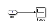
Create an input structure for loading 11 time samples of a two-element signal vector of type
int8into the model:N = 10 Ts = 0.1 a.time = Ts*[0:N]'; c1 = int8([0:1:10]'); c2 = int8([0:10:100]'); a.signals(1).values = [c1 c2]; a.signals(1).dimensions = 2;
In the Configuration Parameters > Data Import/Export > Input parameter edit box, specify the variable
a.In the Inport block dialog box, in the Signal Attributes tab, set Port dimensions to
2and Data type toint8.
As another example, consider a model that has two inputs.
Suppose that you want to input a sine wave into the first port and a cosine wave into
the second port. Define a structure, a, as follows, in the MATLAB workspace:
a.time = 0.1*[0:1]';
a.signals(1).values = sin(a.time);
a.signals(1).dimensions = 1;
a.signals(2).values = cos(a.time);
a.signals(2).dimensions = 1;
Enter the structure name (a) in the Configuration Parameters > Data Import/Export > Input parameter edit box.
Note
In this model you do not need to specify the dimension and data type, because the
default values are 1 and double.
Loading Data Arrays to Root-Level Inputs
You can load to a root-level input port data from the workspace in the form of a data array, which you specify in the Configuration Parameters > Data Import/Export > Input parameter.
This import format consists of a real (noncomplex) matrix of data type
double. The first column of the matrix must be a vector of times in
ascending order. The remaining columns specify input values.
Each column represents the input for a different Inport or Trigger block signal (in sequential order).
Each row is the input value for the corresponding time point.
For a Trigger block, the signal that drives the trigger port must be the last data item.
The total number of columns of the input matrix must equal n + 1,
where n is the total number of signals entering the model input ports.
Specify the Input Expression
The default input expression for a model is [t,u] and the default
input format is Array. If you define t and
u in the MATLAB workspace, simply select the Configuration Parameters > Data Import/Export > Input parameter to input data from the model workspace.
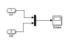
Suppose that you have a model with two Inport blocks:
The
In1block accepts two signals (the block has the Port dimensions parameter set to2).The
In2block accepts one signal (the block uses the default value for the Port dimensions parameter).
You define t and u in the MATLAB workspace:
numSteps = 9;
timeStep = 0.1;
t = (timeStep*(0:numSteps))';
u = [sin(t),cos(t),4*cos(t)];
When the simulation runs, the signal data sin(t) and
cos(t) are assigned to In1 and the signal data
4*cos(t) is assigned to In2. Signal data is input
for 100 time points.
Note
The array input format allows you to load only real (noncomplex) scalar or vector
data of type double. Use the structure format to input complex data,
matrix (2-D) data, and data types other than double.
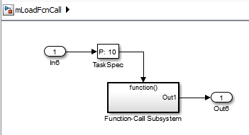
Arrays for Input Ports Driving Function-Call Subsystems
You can use an array to drive a Function-Call Subsystem through a root-level input
port. You can use an array or an array that is an element of a Dataset
object. The array must be an n-by-1 array. For the root-level Inport block,
select the Output function call parameter.
For example, this Dataset object has an array element
x:
ds = Simulink.SimulationData.Dataset;
x = [1 3 7 8]';
ds = ds.addElement(x,'theElementName');
This model uses the ds data set in the Configuration Parameters > Data Import/Export > Input parameter.
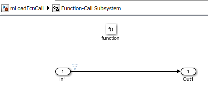
When you simulate the model, the time values of the logged signal data in the
Function-Call Subsystem show that the Function-Call Subsystem was triggered only for the
times specified in an array stored in ds.
>> logsout{1}.Values.Time

ans =

     1
     3
     7
     8
Loading MATLAB Time Expressions to Root Inports
Specify the Input Expression
You can use a MATLAB time expression to load data from a workspace into a root-level input port.
To use a time expression, enter the expression as a string (enclosed in single quotes) in
the Input field of the Data
Import/Export pane. The time expression can be any MATLAB expression that evaluates to a row vector equal in length to the number of
signals entering the input ports of the model. Suppose that a model has one vector Inport
that accepts two signals. Also, suppose that timefcn is a user-defined
function that returns a row vector two elements long. Here are valid input time
expressions for such a model:
'[3*sin(t), cos(2*t)]'

'4*timefcn(w*t)+7'
The expression is evaluated at each step of the simulation, applying the resulting
values to the input ports of the model. Simulink defines the variable t when it runs the simulation. Also,
you can omit the time variable in expressions for functions of one variable. For example,
the expression sin is interpreted as sin(t).
See Also
Blocks
Classes
Topics
- Load Bus Data to Root-Level Input Ports
- Loading MATLAB Timeseries Data to Root-Level Inputs
- Loading Data Arrays to Root-Level Inputs
- Loading MATLAB Time Expressions to Root Inports
- Loading Data Structures to Root-Level Inputs
- Comparison of Signal Loading Techniques
- Loading Data Arrays to Root-Level Inputs