What Are Variants and When to Use Them
What Are Variants?
In Model-Based Design, creating multiple design variations for system components is essential to meet different sets of requirements. These requirements can cater to diverse market needs, customer preferences, or geographical features. Throughout the development lifecycle, from requirements to deployment, you may need to switch between these design choices.
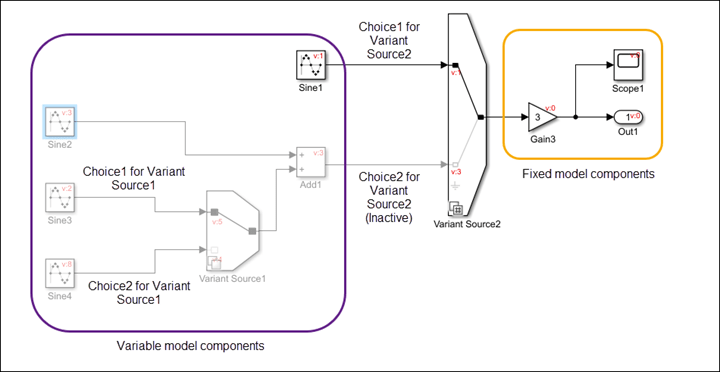
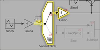
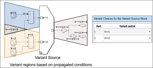
Simulink® variant capabilities allow you to represent all design alternatives of a system in a single model. Each design choice is incorporated into the model as a variant choice. Such models have a fixed common structure and a finite set of variable components that are activated depending on the variant choice. This model shows how Variant Source blocks help you implement variant choices for the input signals to a system. The inactive choice appears faded.
For an example, see Use Variants to Create One Model for Many Systems.
Advantages of Using Variants
Using variants in Model-Based Design provides several advantages:
Variants allow you to design one model for many systems.
You can rapidly prototype design possibilities as variants without having to comment out sections of your model.
Variants help you develop modular design platforms for reuse and customization. This approach improves workflow speed by reducing complexity.
If a model component has several alternative configurations, you can explore the alternatives without altering the fixed components.
You can use different variant configurations for simulation or code generation from the same model.
You can simulate every design possibility for a given test suite.
If you are working with large-scale designs, you can distribute the process of testing these designs on a cluster of multicore computers. Alternatively, you can map different test suites to design alternatives for efficient management of design-specific tests.
You can generate a reduced model for a subset of variant configurations from a model with many variants.
When to Use Variants
Here are three scenarios where you can use variants.
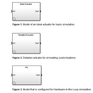
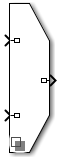
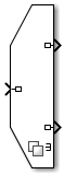
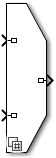
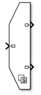
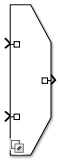
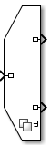
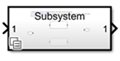
Models that represent multiple simulation, code generation, or testing workflows. |
|
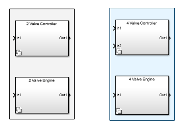
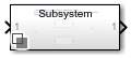
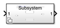
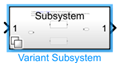
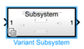
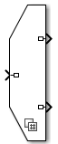
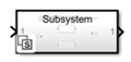
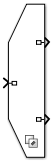
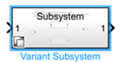
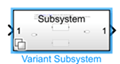
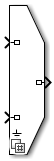
Models that contain multiple design choices at the component level. |
|
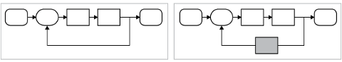
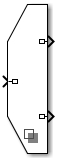
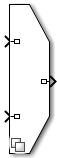
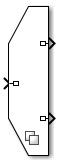
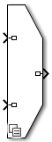
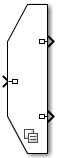
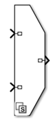
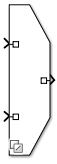
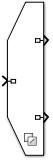
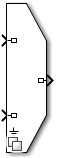
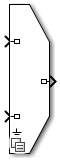
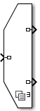
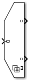
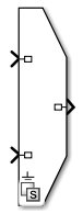
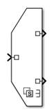
| Models that are mostly similar but have slight variations, such as in cases where you want to separate a test model from a debugging model. The test model on the left has a fixed design. On the right, the same test model includes a variant that is introduced for debugging purposes. |
|
Types of Variants in Simulink
Variant blocks help you represent multiple structural or algorithmic implementations of a system component in a single model and allow you to switch between them as per requirements. For an overview of the types of variant blocks in Simulink, see Variant Blocks in Simulink.
Variant parameters help you implement design variations that require varying values for block parameters. For more information, see Use Variant Parameters to Reuse Block Parameters with Different Values.
Variant transitions allow you to transition to multiple design configurations within the same Stateflow® chart. For more information, see Control Indicator Lamp Dimmer Using Variant Conditions (Stateflow).
Dimension variants allow you to specify symbolic dimensions that vary based on variant conditions. See Implement Symbolic Dimensions for Array Sizes in Generated Code (Embedded Coder).
AUTOSAR variants enable you to use variant blocks to implement AUTOSAR software components with variation points. See Model AUTOSAR Variants (AUTOSAR Blockset).
Tip
For a list of examples that show variant capabilities in Simulink, see V-Model for System Development with Simulink Variants.
To see definitions for key terms and parameters used with variants, see Variant Terminology.
For examples that show variant code generation capabilities, see Variant Systems (Embedded Coder).
Variant Blocks in Simulink
Use these variant blocks depending on the model design:
Hierarchical variant blocks to create multiple implementations of a component in a separate hierarchy in the model.
Inline variant blocks to represent all variant implementations at the same level in the model.
Event-based variants to use variants to model context-dependent system behaviors.
| Type of Variant | Variant Block | Use |
|---|---|---|
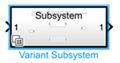
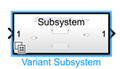
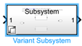
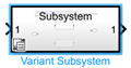
| Hierarchical variant blocks | Variant Subsystem | The Variant Subsystem block is a template preconfigured with Subsystem blocks to represent the variant choices. The Variant Subsystem block allows a combination of Subsystem blocks, Model blocks, or Subsystem Reference blocks as variant choices. |
| Variant Model | The Variant Model block is a template preconfigured with two Model blocks to represent the variant choices. The Variant Model block allows a combination of Subsystem blocks, Model blocks, or Subsystem Reference blocks as variant choices. | |
| Variant Assembly Subsystem | The Variant Assembly Subsystem block enables you to add or remove its variant choices from external files. The Variant Assembly Subsystem allows a combination of Model blocks, or Subsystem Reference blocks as variant choices. | |
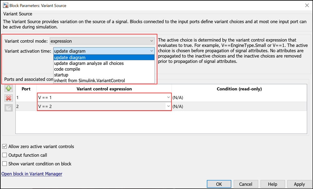
| Inline variant blocks | Variant Source | The Variant Source block allows you to define variant choices as block regions connected to each of its inports. The block provides variation on the source of a signal. |
| Variant Sink | The Variant Sink block allows you to define variant choices as block regions connected to each of its outports. The block provides variation on the destination of a signal. | |
| Variant Start | The Variant Start block allows you to define the start of the bounded region. You can limit the variant condition propagation in the bounded region. Every Variant Start block has a corresponding Variant End block. | |
| Variant End | The Variant End block allows you to define the end of the bounded region. You can limit the variant condition propagation in the bounded region. | |
| Manual Variant Source | The Manual Variant Source block is a toggle switch that allows you to define multiple variant choices at its inports. | |
| Manual Variant Sink | The Manual Variant Sink block is a toggle switch that allows you to define multiple variant choices at its outports. | |
| Variant Connector (Simscape) | The Variant Connector block lets you define variant choices in a physical network. You can switch between components in the network during simulation without having to physically remove the components or exclude them from simulation. | |
| Event-based variants | Simulink Function | The variant functionality in the Simulink Function block allows the block to be conditionally available. You can specify variant conditions on the function call port block or the block can inherit the condition from its function caller blocks. |
| Initialize Function, Reset Function, and Terminate Function blocks | The variant functionality in Initialize, Reset, and Terminate blocks allow the blocks to be conditionally available. You can specify variant conditions on the event listener block. |
Compare Variant Blocks
This table presents a comparison between hierarchical and inline variant blocks.
| Feature | Variant Source and Variant Sink blocks | Variant Subsystem and Variant Model blocks |
|---|---|---|
Variant choice representation | Number of ports | Subsystem, Model, or Subsystem Reference blocks |
Allows to implement variant choices in a separate hierarchy | No | Yes |
Supports flexible number of inputs and outputs among variant choices (the choices do not have similar interface) | No | Yes, if the Propagate conditions outside of variant subsystem
parameter is set to |
Option to specify default variant | Yes | Yes |
Supports control ports | No | Yes |
Can be saved as standalone file | No | No |
Supports Connection Port used for modeling physical connection lines | No | Only when the Variant activation time parameter is
set to |
Comment a variant choice (by adding the | No | Yes |
Use Variants to Create One Model for Many Systems
This example shows variant design in a Simulink model. Consider the requirement to model a system that represents an automobile with several configurations. These configurations, although similar in several aspects, can differ in properties such as fuel consumption, motor type, or emission standard.
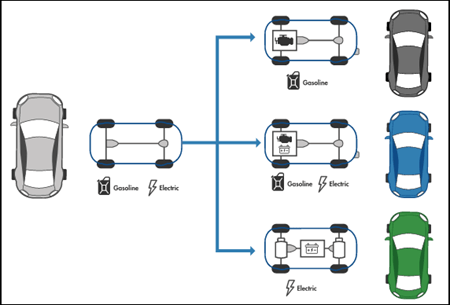
Instead of designing separate models for each configuration, you can represent the configurations as variant choices in a single model. You can choose to activate any one of the variant choices based on your requirements. This approach keeps the common components fixed.
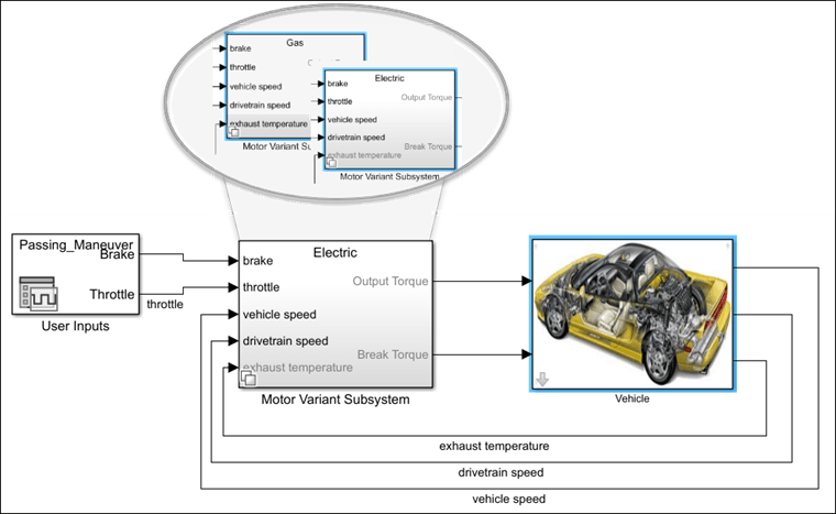
This model contains a Variant Subsystem block, Motor Variant
Subsystem, that represents the motor of the vehicle. The motor has two possible
configurations, Gas and Electric, that are represented
as variant choices within the Variant Subsystem block. A Variant
Subsystem block adapts its interface according to the state of the underlying
blocks. Here, the Electric motor does not have an exhaust
temperature input. When you activate the Electric variant,
Simulink automatically disables the corresponding port on the Motor Variant
Subsystem and any other model components associated with that input.
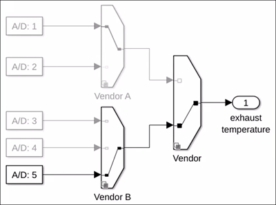
For the exhaust temperature sensor for this model, consider the need
to switch between five different sensors provided by two vendors. You can use Variant
Source blocks to represent all the choices in the same model and activate only one
choice at a time.
Working with Variants
Visual Elements in Variant Models
| Visual Element | Use |
|---|---|
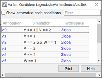
| Variant Condition Legend | The Variant Condition Legend dialog box helps you visualize the variant conditions applied on the model. Simulink annotates model components that have variant conditions, and the Variant Condition Legend displays the conditions for each annotation. See Visualize Propagated Variant Conditions in Variant Conditions Legend.
|
| Variant Badges | Each variant block displays a badge that changes with different parameter values set on the block. See Variant Badges.
|
| Variant Fading and Signal Highlighting | The color of inactive variant choices fades by default. You can choose to disable the fading effect by using the Variant Fading option in the Information Overlays menu on the Debug tab of the Simulink Editor. Highlighting a signal that passes through variant blocks highlights the path of the active variant choice. See Signal Highlighting in Variant Systems.
|
Variant Badges
Each variant block displays a badge. The color and icon of the variant badge changes according to values of these parameters set on the block:
Variant activation time
Variant control mode
Allow zero active variant controls (for Variant Source and Variant Sink blocks)
Propagate conditions outside of variant subsystem (for Variant Subsystem block)
Variant Badges also provide quick access to some variant commands. Right-click the variant badge to access these commands.
Note
The Refresh Blocks (Ctrl+K) option on the variant badge does not re-evaluate the variables that are defined in the mask workspace of the variant blocks. For example, consider a masked Variant Subsystem block with the variant control variable defined in the mask workspace of the block. To change the active choice of the block, you change the value of the variant control variable. When you then click the Refresh Blocks (Ctrl+K) option, the variant control variable is not re-evaluated and so the active choice of the block is not updated. You must click Apply on the mask dialog box or update the diagram for the latest active choice to reflect.
![]() Variant Badge Icons for Different Settings on Variant Blocks
Variant Badge Icons for Different Settings on Variant Blocks

Define and Control Variant Choices
You must associate each variant choice in a model with a variant control that is used to determine if the choice is active or inactive. For variant blocks, you can choose the mode in which you want to specify the variant controls using the Variant control mode parameter. For more information, see Introduction to Variant Controls.
Automatically Identify Variant Regions Using Variant Condition Propagation
Simulink determines the model components that are active during simulation by the process of variant condition propagation. This process evaluates the variant controls specified on the variant blocks and automatically propagates the variant conditions to the connecting blocks. Variant conditions can propagate through signal lines, buses, and function calls. The process deactivates the model components associated with the inactive choices and they are not included in simulation. You can stop condition propagation to define variant regions in the model using the Variant Start and Variant End blocks. See Propagate Variant Conditions to Define Variant Regions with Variant Blocks.
Choose a Variant Activation Time
You can also choose when the active variant choice is determined using the Variant activation time parameter. This parameter also determines how the active and inactive choices participate in the simulation and code generation workflows. See Activate Variant During Different Stages of Simulation and Code Generation Workflow.
Note
You can choose the variant activation time for a variant block only when
Variant control mode is set to
expression.
Manual Variant Source and Manual Variant Sink blocks do not support variant controls and variant activation time. They determine the active variant choice based on the active inports and outports, respectively.
Variant Connector blocks do not support variant activation time.
Manage All Variants Using Variant Manager
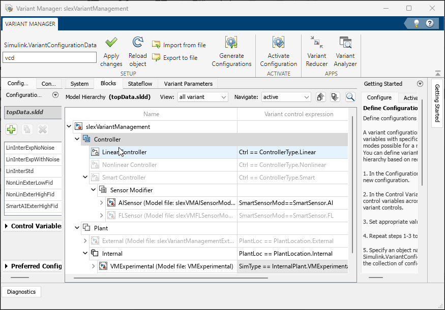
Variant Manager is a tool that allows you to visualize the model hierarchy and centrally manage the usage of variant elements across the hierarchy.
The tool is available as a support package named Variant Manager for Simulink with these main capabilities:
Variant Manager — Visualize the model hierarchy, manage the usage of variant elements across the hierarchy, create and manage variant configurations.
Variant Reducer — Generate a reduced model that contains only selected variant configurations.
Variant Analyzer — Compare and contrast variant configurations to identify errors or inconsistencies.
Create and Activate Variant Configurations:
A model hierarchy may contain several variant blocks, each with many variant choices. Combinations of these variant choices correspond to specific configurations of the system. Switching between these configurations and validating them manually can be complicated and can introduce errors. You can use the Variant Manager to create and save variant configurations for a model and run the model under any of the configurations. You can also validate the configurations against a set of constraints.
Analyze and Reduce Variant Configurations:
You can use the Variant Analyzer tool in the Variant Manager to compare variant configurations for a model and to determine which blocks are used in each configuration. The tool helps in model verification and validation workflows because it can identify unused regions in the model.
You can use the Variant Reducer tool in the Variant Manager to automatically generate
a reduced model for a subset of variant configurations and analyze the reduced model in a
detailed report. The reduction process removes inactive components for the specified
variant configurations. Variant Reducer reduces associated model references, subsystem
references, and libraries in the model. The tool also reduces any dependent artifacts,
such as MAT or .sldd files, and packages all the reduced artifacts in a
specified output folder.
Generate Code from Variant Models
You can use Simulink Coder™ or Embedded Coder® to generate code from variant models. See Prepare Variant-Containing Model for Code Generation.
For examples that show variant code generation capabilities, see Variant Systems (Embedded Coder).
See Also
Topics
- V-Model for System Development with Simulink Variants
- Create a Simple Variant Model
- Create a Simple Variant Parameter Model
- Create and Activate Variant Configurations
- Implement Variations in Separate Hierarchy Using Variant Subsystems
- Variant Source and Variant Sink Blocks
- Control Indicator Lamp Dimmer Using Variant Conditions (Stateflow)
- Transform Model to Variant System (Simulink Check)
- Variant System Design
- Variant Terminology
- Introduction to Variant Controls
- Working with Variant Choices
- Create and Activate Variant Configurations
- Managing Design Variants
- Using Variant Subsystems (3 min, 38 sec)
- Variant Source and Sink Blocks with Condition Propagation
- Variant Condition Propagation
- Variant Configuration Management
- Generate Code from Variant Source and Sink Blocks
- Model AUTOSAR Variants