Use Variants in Automotive Assembly Line Production
In an automotive manufacturing company, the production line assembles different vehicle models, such as a standard sedan, an SUV, and a sports car, on the same assembly line. Many components and assembly steps are shared across all models, but certain parts, like the Engine Control Unit (ECU), require vehicle model-specific configurations to meet unique performance and regulatory needs. In the physical factory, workers and machines choose different these components as each vehicle moves down the line so that every car receives the correct ECU and other specialized component.
You can automate the management of these variations through software modeling. Instead of creating separate models for each vehicle configuration, you can represent shared elements once in a single model and use Simulink® variants to manage the differences. Variants act as virtual switches that enable you to define multiple ECU configurations or other unique features within the same model. By selecting a specific variant, you automatically activate the corresponding configuration.
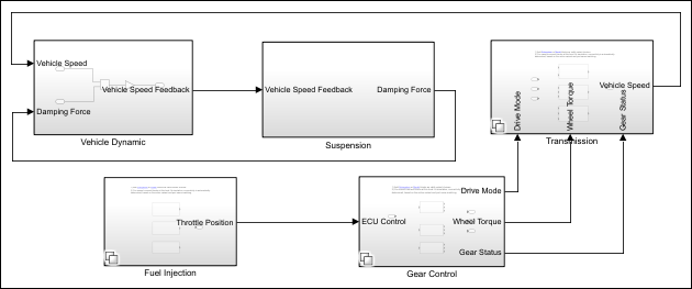
Consider this diagram illustrating a vehicle ECU system that uses the Variant
Subsystem blocks Suspension, Transmission,
Fuel Injection, and Gear Control. In the
Suspension block, the variable surfaceAdaptationGain
represents a variant parameter whose value changes based on driving conditions. This setup
involves structural and parameter variations across multiple vehicle types including sedans,
SUVs, and sports cars.
The table representing the Variant Manager for Simulink support package lists the configurations that define combinations of these
variations. Each configuration specifies options such as fuel injection method, transmission
type, gear control mode, and surface adaptation gain for conditions such as
vehicleType == sedan, vehicleType == SUV, and
vehicleType == sport. In this example, the configuration for SUV is
selected, which activates the Direct fuel injection,
Automatic transmission, and Terrain gear control
within the Variant Subsystem blocks, and sets the Surface Adaptation
Gain value to 1.
After developing and validating the software model with its variants, you can generate production-ready code for each configuration. This code is then compiled and flashed onto the target hardware, such as the ECU, during manufacturing. On the assembly line, as each vehicle is identified by, for example, customer order, the correct software variant is selected and loaded onto the vehicle’s ECU.
Represent Variations in Vehicle Engine Control Unit
This section explains how to use variant blocks, variant parameters, and variant dimensions to represent structural, value, and dimension variations of an ECU in Simulink. While some components of the ECU remain fixed across all configurations, these variant mechanisms enable you to specify and manage the parts that differ.
Structural Variation to Represent Vehicle Models
With variant blocks in Simulink, you can manage design variations within a single model, eliminating the need for separate models for similar systems. Use variant blocks in applications where different versions of a product share common components but require modifications for specific features. For more information, see Switch Between Model Structures.
You can use variant blocks to represent ECU configurations for various vehicle types.
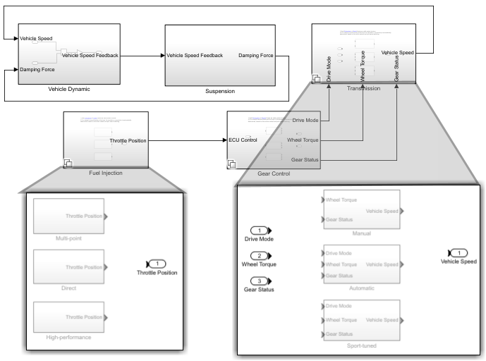
For example, use the Variant Subsystem block Fuel
Injection to represent the fuel injection system for different types of
vehicles.
The fuel injection system can be of three types:
Multi-pointfor the sedan modelDirectfor the SUV modelHigh-performancefor the sport model
These types are represented as variant choices within the Fuel
Injection block. You can specify the variant condition for each choice by
assigning a logical expression such as:
vehicleType == sedanfor the sedan modelvehicleType == SUVfor the SUV modelvehicleType == sportfor the sport model
Similarly, you can use the Variant Subsystem block to
represent the transmission system that can be Manual for the sedan,
Automatic for the SUV, and Sport-tuned automatic
for the sport model.
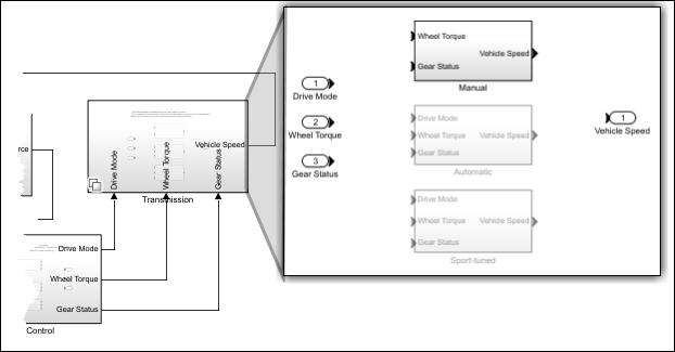
The Variant Subsystem block, for example, the
Transmission block, adapts its interface according to the state of
the underlying Manual, Automatic, and
Sport-tuned variant choices. Here, the Manual
block does not have a Drive Mode input. When the
Manual variant choice is active, Simulink deactivates the Drive Mode sensor port on the
Transmission block and any other model elements associated with that input.
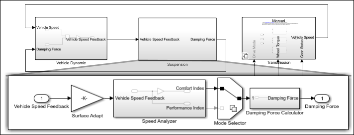
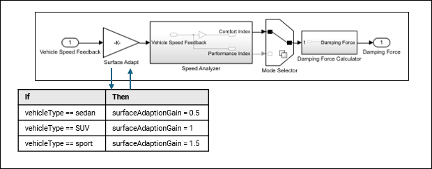
In the Suspension system, the Speed Analyzer
block computes two values from vehicle speed, Comfort Index and
Performance Index. The Variant Source block,
Mode Selector, then compares the Comfort Index to
a predefined threshold value to determine the optimal damping force.
If the
Comfort Indexexceeds the threshold, the system uses theComfort Indexvalue in theDamping Force Calculatorto determine the optimal damping force for a smoother ride for the sedan model.If the
Comfort Indexis below the threshold, the system uses thePerformance Indexvalue in theDamping Force Calculatorto determine the optimal damping force for a firmer ride for the SUV and sport models.
In this scenario, since the Comfort Index surpasses the
threshold, so it is selected and used to compute the optimal damping force. The
Performance Index remains inactive.
Parameter Variation to Represent Ignition Timing
With variant parameters in Simulink, you can specify multiple values for a parameter within a single model instead of creating separate models. Use variant parameters when similar systems share a common structure but vary in their parametric values, such as different gain settings or threshold values. For more information, see Change Parameter Values.
You can use a variant parameter, surfaceAdaptionGain, in the
Suspension system to adjust its response for minimal vibration under
different road conditions. This parameter takes different values depending on the vehicle
type to achieve optimal suspension performance. For example:
If
vehicleType == sedan, thesurfaceAdaptionGainvalue is0.5.If
vehicleType == SUV, thesurfaceAdaptionGainvalue is1.0.If
vehicleType == sport, thesurfaceAdaptionGainvalue is1.5.
Dimension Variation to Represent Suspension Sensors
With variant dimensions, you use symbols instead of fixed numbers to assign different sizes to the same signal without changing the model structure. For more information, see Adapt Signal Dimensions.
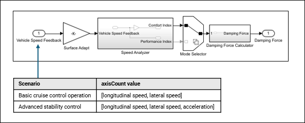
You can use variant dimensions to manage vehicle speed feedback when its size changes.
For example, specify the port dimension of the Vehicle Speed Feedback
input as axisCount. During basic cruise control operation,
axisCount might include only longitudinal and lateral speeds, while
in advanced stability control scenarios, it could also include acceleration as a third
value. By using variant dimensions, the model can adapt to these variations in vehicle
speed feedback size without requiring separate models for each case. The Inport
block Vehicle Speed Feedback with varying port dimensions,
mapped to corresponding values in the table for different control scenarios.
Synchronize Structural and Parameter Variations Specific to Vehicle Model
You can use a single variant control to synchronize the structural and parameter variations to minimize the discrepancies and errors that can arise from managing the variations separately.
To synchronize structural and parameter variations for the SUV model, apply the same
condition vehicleType == SUV in the Variant Subsystem block
Transmission and the damping coefficient
surfaceAdaptionGain. When vehicleType is set to
SUV, the model activates the Automatic transmission
structure and assigns surfaceAdaptionGain a value of
1. This unified control maintains consistency across the model because
structural and parameter changes are aligned under a single condition. A single variant
control mechanism also simplifies managing variations by requiring you to update only one
variant control to switch between different variations.
Create and Manage Vehicle Configurations Using Variant Manager
The Variant Manager for Simulink support package provides a centralized way to visualize the model hierarchy, manage variant elements by grouping them into meaningful combinations called variant configurations, and define system-wide constraints. You can validate these configurations against system-wide constraints to prevent invalid modes of operation. The support package also enables you to reduce models to specific configurations and analyze variations for consistency.
For example, while developing the model, you can define multiple ECU configurations for
different vehicle models, such as sedans, SUVs, or sports cars in the Variant Manager for Simulink support package. During simulation, you select the appropriate configuration,
such as Sports, and also validate it to apply the correct fuel injection,
transmission, and suspension settings for that vehicle. The support package enables you to
switch between different vehicle models without manually activating or deactivating
individual variant elements.
After validation, you can generate code using Embedded Coder® or Simulink Coder™, which is then compiled and flashed onto the target ECU hardware to implement the same logic as in the software environment. For more information, see Variant Manager for Simulink.