Simulink Variants Overview
R2026bVariants in Simulink® enable multiple design alternatives of a system to coexist in a single model, eliminating the need for separate models and facilitating reuse of model elements and artifacts. You can transition between variations by setting a variable in the workspace before simulation, choosing a variant through a user input such as a parameter or dialog box, or allowing the model to automatically select the appropriate design based on the hardware platform you are targeting.
In Simulink, you can implement design variations using variant blocks, variant parameters, or symbolic dimensions. Use variant blocks to implement structural or algorithmic variations within your model, such as different controllers or plant models. Use variant parameters to implement variations in parameter values, for example, different gain values or physical constants. Use symbolic dimensions to implement variability in signal dimensions, such as the size of an input or output port based on the selected alternative.
A meaningful combination of these variations is defined and managed as a variant configuration. Using the Simulink Variant Manager (Simulink Variant Manager) app, you can define multiple variant configurations and system-wide constraints. You can then apply these configurations across the model hierarchy to switch between them, reducing the complexity and potential errors that can occur when configuring each variant element individually.
Organizations can use variant configurations in their design of product lines such as automobiles, aircraft, or electronics that satisfy diverse market needs, customer preferences, and geographic requirements on a common platform. For instance, in the automotive sector, variants capture differences in parameters such as fuel consumption, emission standards, and so on, within a single model, thus reducing design redundancy, enabling consistent testing across design variations, and simplifying maintenance by integrating updates throughout the model.
Simulink variants integrate into every stage of the development process, from the design phase to code generation and up to the testing phase of the V-model in Model-Based Design as described in V-Model for System Development with Simulink Variants. During the design phase, variants allow you to incorporate multiple design alternatives into a single model using variant blocks, variant parameters, and symbolic dimensions. While designing, you can use Simulink Variant Manager™ to automatically generate variant configurations for all possible valid combinations of variant choices. You can use the app to prevent invalid variant combinations and to reduce the variant model to contain only the selected variants. As development advances to the testing phase, you can use products such as Simulink Design Verifier™ and Simulink Test™ to test variant configurations against their specific requirements.
Advantages of Using Variants in Model-Based Design
This section lists the advantages of using variants, such as creating multiple design variations within a model, centrally configuring variants using Variant Manager, generating common and variant-specific code for deployment, and efficiently testing and validating design alternatives across large and complex systems.
Design Flexibility and Modularity
You can create multiple design variations within a single model to improve flexibility and modularity by using variants. Some key advantages include:
Representing design alternatives within a single model, enabling you to switch between different configurations without maintaining multiple models
Rapidly prototyping design possibilities as variants without creating a separate implementation for each design
Developing modular designs for reuse and customization, reducing complexity
Exploring alternatives without altering the fixed components
This diagram illustrates a system with varying modes Eco mode and
Sport mode for driving, enabling switching between design
alternatives and rapid prototyping within a single model.
Variant Management and Workflow
Using Simulink Variant Manager provides a centralized interface to manage variant configurations and constraints across your model. When you switch between design alternatives, the associated settings update consistently, reducing manual errors and streamlining testing, debugging, and code generation for complex systems. You can also generate a reduced model that uses only a subset of variant configurations from a model with design alternatives.
In this diagram, the table shows how Simulink
Variant Manager maps variant configurations EconomyStandard,
PerformancePlus, and EconomyEnhanced to
combinations of drive modes Eco or Sport, and
sensors Basic or Advanced. The blocks show varying
elements for drive mode and sensor. By using Simulink
Variant Manager, you can select the desired alternative for each element within a particular
configuration. For example, when you select the EconomyEnhanced variant
configuration, Variant Manager selects Eco for the driving mode and
Advanced for the sensor.
Variant Code Generation Capabilities
You can generate common and variant-specific code to reuse, share code with third parties, and deploy code across different systems using variants. Several key advantages include:
Reusing code for a group of models that have similar functionality but small differences
Sharing code generated from a model containing multiple design variations to third parties, allowing them to select and use the variant that best fits their needs
Generating code for one or all variants and easily switching the active variant at compile time, system initialization, or run time, depending on your deployment workflow
Automatically generating code specific to each variant, reducing manual effort and ensuring accurate implementation of functionality specific to each variant
This diagram illustrates a system with varying drive modes,
Eco and Sport, and sensors,
Basic and Advanced, along with the corresponding
generated code. The generated code includes common code for fixed elements and
variant-specific code for variant configurations EconomyStandard,
PerformancePlus, and EconomyEnhanced. When you
compile the code for EconomyEnhanced, the resulting executable includes
the common code and only the code specific to the Eco mode and the
Advanced sensor. To compile code for a different variant
configuration, such as EconomyStandard, you do not have to regenerate
the code. You select the variant configuration EconomyStandard prior to
compilation, and the code generator produces an executable tailored for
EconomyStandard by including the common code and only the code
specific to the Eco mode and the Basic sensor.
Testing and Large-Scale Design
You can manage and validate multiple design alternatives by integrating variant testing into your workflow. Several key advantages include:
Simulating every design possibility for a given test suite
Distributing the testing process for large-scale designs across a cluster of multicore computers
Mapping different test suites to design alternatives for efficient management of design-specific tests
Tip
Limit variants during large-scale design and testing to reduce complexity and validation effort, avoid longer test times, and reduce maintenance overhead.
This diagram illustrates how a test suite connects to multiple design alternatives for
efficient variant testing. The test suite includes drive mode selection and actions that
are mapped to variant configurations EconomyStandard,
PerformancePlus, and EconomyEnhanced. This setup
enables you to test different configurations, distribute tests across multicore clusters,
and map test suites to design alternatives efficiently.
Variant Implementation Techniques in Simulink
You can use several variant implementation techniques in Simulink to manage design alternatives within a single model.
Switch Between Model Structures
Use hierarchical variant blocks to encapsulate multiple implementations of a component in a separate hierarchy of the model.
| Variant block | Use |
|---|---|
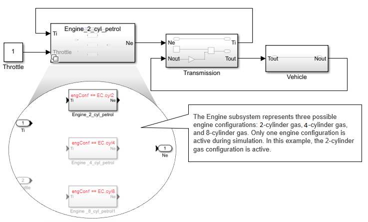
| Variant Subsystem | The Variant Subsystem block provides a structured hierarchy where each design variation is encapsulated within its own subsystem, enabling you to add or remove variations directly within the block. You can switch between the variations using variant controls. For information on how to use a Variant Subsystem block, see Implement Structural Variations with Variant Subsystems in a Separate Model Hierarchy. You can use Variant Subsystem blocks to synthesize hardware design alternatives into hardware description language (HDL) code and to generate C/C++ code for software design alternatives. For more information, see Usage of Different Subsystem Types (HDL Coder) and Generate Code for Variant Subsystem Blocks (Simulink Coder). This diagram illustrates a vehicle with three possible engine
configurations:
|
| Variant Assembly Subsystem | The Variant Assembly Subsystem block is an alternative configuration of the Variant Subsystem block that enables you to manage design variations in a model by using an external source such as an enumeration class or a MATLAB® function without modifying or accessing the model itself. For more information, see Add or Remove Variant Choices of Variant Assembly Subsystem Blocks Using External Files. |
Note
If you have a Subsystem block within your model and need
to incorporate multiple design alternatives, use the Simulink.VariantUtils.convertToVariantSubsystem function to convert the
Subsystem block into a Variant Subsystem block. If you
want to manage multiple design alternatives from external sources, use the Simulink.VariantUtils.convertToVariantAssemblySubsystem function to
convert it into a Variant Assembly Subsystem block.
Switch Between Signal Paths
Use Inline variant blocks to select or route signals between multiple inputs or outputs, and implement design variations at specific signal paths or blocks without adding subsystem hierarchies. Although an inline variant block does not create a new model hierarchy, its effect can extend into hierarchical elements such as Model blocks that exist in the signal path.
| Variant block | Use |
|---|---|
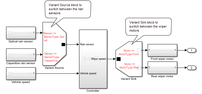
| Variant Source and Variant Sink | The Variant Source block enables you to connect multiple source signals to its input ports, with each port representing a distinct variation. Similarly, the Variant Sink block enables you to connect multiple destination signals to its output ports, with each port representing a distinct variation. You can switch between the variations using variant controls. For more information, see Visualize Variant Implementations in a Single Layer. You can generate C/C++ code from Variant Source and Variant Sink blocks as described in Generate Code for Variant Source and Variant Sink Blocks (Simulink Coder). This diagram illustrates a rain-sensing wiper control system. In this
system, the Variant Source block selects either the optical
rain sensor or the capacitive rain sensor as input, depending on whether the
value of the
|
| Manual Variant Source and Manual Variant Sink | The Manual Variant Source and Manual Variant Sink blocks are similar to the Variant Sink and Variant Source block, but instead of using variant controls to switch between design variations, you toggle between two variations by double-clicking the block. For more information, see Provide Variation in Signal Source and Destination Using Manual Variant Source and Manual Variant Sink Blocks. |
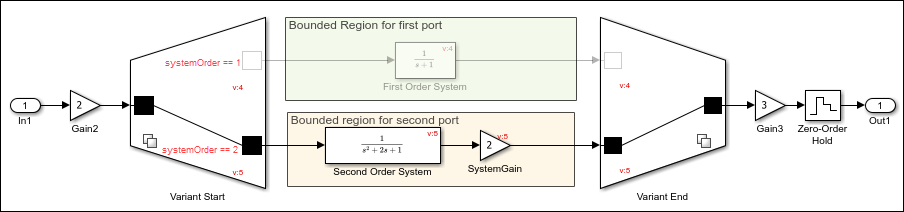
| Variant Start and Variant End | The Variant Start and Variant End blocks create a bounded region to control activation and deactivation for a specific set of blocks. These blocks collectively confine activation and deactivation to the region and do not impact other parts of the model. If you have elements with varying inputs, outputs, or functionalities that would typically require a Variant Subsystem block, but you want the variant choices to appear in a single level of the model hierarchy, place a Variant Start block at the entry and a Variant End block at the exit of the variant path. For more information, see Limit Variant Condition Propagation Within Bounded Regions Using Variant Start and Variant End Blocks. You can generate C/C++ code from Variant Start and Variant End blocks as described in Generate Code for Variant Start and Variant End Blocks (Simulink Coder). This diagram represents a control system that includes first-order and
second-order systems. The systems are placed within the bounded region
defined by the Variant Start and Variant End
blocks. These variant blocks activate the blocks in the first-order system
if the
|
Change Parameter Values
You can conditionally vary the values of block parameters in a Simulink model by using a variant parameter. To create a
variant parameter object, use the Simulink.VariantVariable class. This object defines a set of values, known
as choices, and variant condition expressions associated with the choices. To specify the
variant condition corresponding to each choice of the variant parameter, use a variant
control variable of type Simulink.VariantControl. Use the
Simulink.VariantControl object to specify an activation time for
the variant parameter and set a value to evaluate the variant conditions and determine the
active choice of the variant parameter. During simulation, the choice associated with the
variant condition that evaluates to true becomes the active value of the variant
parameter.
For an overview of variant parameters, see Use Variant Parameters to Reuse Block Parameters with Different Values. Variant parameter objects support the generation of C/C++ code as described in Options to Represent Variant Parameters in Generated Code (Simulink Coder).
Consider this model that represents an automobile system with several
configurations. These configurations, although similar in several aspects, can differ in
values such as fuel consumption rate, engine size, or number of cylinders in the engine.
Instead of designing multiple blocks that together represent all possible
configurations, you can use variant parameters to model the varying values. In this
model, the Fuel consumption, Engine size, and
Number of cylinders blocks have variant parameters
fc, es, and nc. The values of
the variant parameters are based on the value of the variant control variable
V. For example, if V == 1 evaluates to
true, then fc is set to 30,
es is set to 1000, and nc is
set to 4.

Switch Based on Events or Triggers
Use event-based variants when creating complex models where the execution of certain components depends on the state or activity of other components. Event-based variants include both conditionally executed subsystems and event function blocks.
A conditionally executed subsystem is a nonvirtual subsystem whose execution is controlled by an external signal. By specifying variant conditions in conditionally executed subsystems, you can control whether or not to provide the external signal to the subsystem.
An event function block allows you to add custom routines to the default routines. By specifying variant conditions in event function blocks, you can control whether these custom routines are executed.
| Event function and conditionally executed subsystem | Use |
|---|---|
| Enabled Subsystem, Triggered Subsystem, Reset, and Function-Call Subsystem | Conditional subsystems such as Enabled, Triggered, Reset, and Function-Call blocks control execution tasks such as state initialization, value resetting, and cleanup in response to external signals. With variant blocks, you can selectively provide these signals to the conditional subsystem blocks. For more information, see Propagate Variant Conditions to Control Execution of Conditional Subsystems. This diagram illustrates how to merge the distinct function‐call signals from different ports into a single, unified output. The Pulse Generator block drives a Variant
Subsystem block that contains two charts,
|
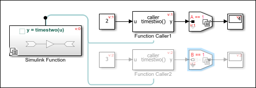
| Simulink Function | You can control the execution of functions defined in the Simulink Function blocks by conditionally invoking them with a Function Caller block. To determine which function executes, you can either specify a condition for each function for individual control or inherit the condition from the caller block for centralized management through the Function Caller block. For more information, see Conditionally Execute Simulink Functions. This diagram illustrates the conditional execution of a Simulink Function block. The Trigger Port block within the Simulink
Function block has the Enable variant condition
parameter selected, and the Variant control parameter set
to
|
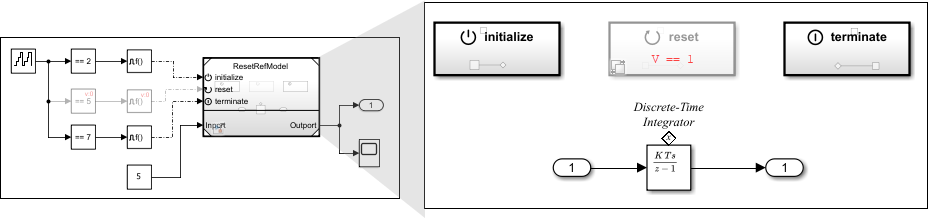
| Initialize Function, Reset Function, and Terminate Function | You can control the execution of the Initialize Function, Reset Function, and Terminate Function blocks by conditionally providing the signals to execute actions such as initializing states, resetting values, or performing cleanup. For more information, see Conditionally Execute Custom Initialize, Reinitialize, Reset, and Terminate Routines. This diagram illustrates conditional activation of the reset signal. The Event Listener block within the Reset
Function block has the Enable variant condition
parameter selected and the Variant control parameter
specified as
|

Adapt Signal Dimensions
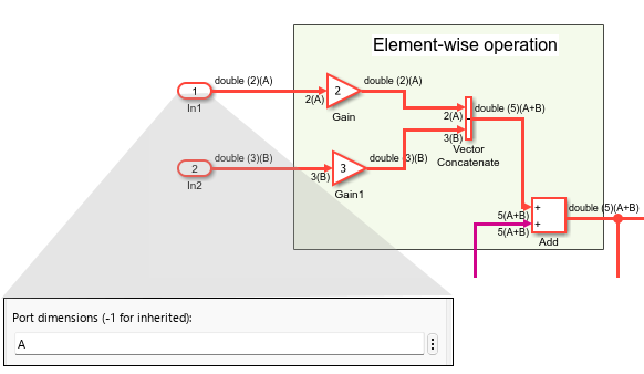
Symbolic dimensions allow you to use symbols instead of fixed numbers to specify signal sizes. Use symbolic dimensions to assign different dimensions a signal without changing the model structure. See Use Symbolic Signal Dimensions. You can generate C/C++ code for models that use variant dimensions as described in Implement Symbolic Dimensions for Array Sizes in Generated Code (Embedded Coder).
This diagram illustrates the use of a symbolic dimension to represent the dimension
of a signal in a model. By assigning the port dimension to a symbolic variable
A, the model can accept input signals of varying sizes, such as
vectors, matrices, array sizes, and so on.
Control Bus Signal States with Variants
Buses group multiple signals or messages into a single entity, simplifying block
diagrams and reducing clutter. The signals within a bus can have variant conditions that
are propagated from connected variant blocks. If the variant condition for a signal
evaluates to true, the signal is active. Otherwise, the signal is
inactive. For more information, see Variant Elements Within Buses. To learn about
generating C/C++ code for models that use variant blocks with buses, see Generate Code for Variant Elements Within Buses (Simulink Coder).
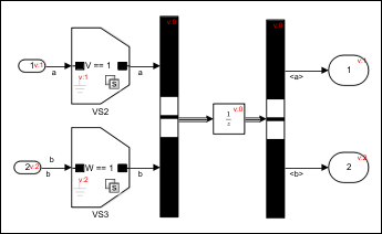
This diagram illustrates buses with elements that have different variant conditions.
The model consists of two signals, a and b, which
are merged to form a bus. These signals have variant conditions, V ==
1 and W == 1 respectively. During simulation, if the
variant condition V == 1 evaluates to true, the
signal a is active. Otherwise, it is inactive.
Choose Between Inline and Hierarchical Variant Blocks
You can select between variant blocks based on factors such as hierarchy support, interface flexibility, default variant specification, control ports, and so on. This table compares hierarchical and inline variant blocks.
| Feature | Variant Source and Variant Sink) | Variant Subsystem | Variant Assembly Subsystem | Implementation |
|---|---|---|---|---|
| Variant choice representation | Number of ports | Subsystem, Model, or Subsystem Reference blocks | Model, or Subsystem Reference blocks | Use the Variant Source and Variant Sink blocks for signal routing, switching, or granular variation when the design variations have the same interface and only signal switching is needed. Use the Variant Subsystem block for encapsulating complex, modular, or reusable logic when the design variations require different interfaces. If you also need to manage design variations by using an external source without modifying or accessing the model, use the Variant Assembly Subsystem block. |
| Implementation of variant choices in a separate hierarchy | No | Yes | Yes | Use the Variant Subsystem or Variant Assembly Subsystem block to organize large models or when each design variation is a distinct subsystem or model component. |
| Flexible number of inputs and outputs among variant choices (choices do not have similar interface) | No | Yes, if Propagate conditions outside of variant subsystem is selected | Yes, if Propagate conditions outside of variant subsystem is selected | Use the Variant Subsystem or Variant Assembly Subsystem block when design variation have different signal requirements or structures. |
| Option to specify default variant choice | Yes | Yes | No | Use the Variant Source, Variant Sink, or Variant Subsystem block to specify a default variant choice that becomes active when no variant choice is active, for example, to implement fallback logic. |
| Control signal support | Yes, only for single-input, single-output (SISO) blocks through data ports. | Yes, through control ports | Yes, through control ports | Use control signals when you need to manage enable, trigger, or reset signals as part of the design logic. |
| Connection Port (Simscape) support used for modeling physical connection lines | No | Yes, only when Variant activation time is set to
update diagram | Yes, only when Variant activation time is set to
update diagram | Use the Variant Subsystem or Variant Assembly Subsystem block for physical modeling, for example, in Simscape™, when the connection ports are required. |
Commenting out a variant choice by adding the % symbol
before the variant control in the Block Parameters dialog box | No | Yes | No | Use the Variant Subsystem or Variant Assembly Subsystem block for advanced variant management, such as temporarily disabling design variations during development or testing. |
Note
You can also comment out or comment through certain elements of your model to exclude from simulation without removing them. To do so, select a model element and hover over the three dots. In the action menu that appears, select Comment Out or Comment Through.
When you comment out a block, the block is disabled and its input signals do not propagate through the model. Use Comment Out to temporarily disable a block without affecting the rest of the model.
When you comment through a block, the block is bypassed, but the signals continue to propagate through the model. Use Comment Through to exclude a block from simulation while still allowing the signals to reach downstream blocks.
Unlike variant blocks, the Comment Out and Comment Through options are not controlled by variant logic, require manual changes to switch, are not reflected in generated code, and are intended primarily for testing purposes.
When you comment out or comment through a block in a library, the commented status does not apply to instances of that block in models. Model instances continue to simulate without warnings and you have no indication that the block is commented out or commented through in the library.
For more information, see Comment Out and Comment Through Blocks.
For variant choices in hierarchical variant blocks, the Comment
Out and Comment Through options are not
available. To comment out a variant choice, add a % before the
variant choice name in the block parameters dialog box.
Apply Variants in Simulink-Based Modeling Domains
You can extend variant techniques beyond Simulink models to applications in Stateflow®, AUTOSAR Blockset, Simscape, and System Composer™, maximizing reusability and scalability for evolving design requirements.
Variants in Stateflow chart — Variant transitions allow you to define and switch between multiple design variations using variant controls within the same Stateflow chart. For more information, see Control Indicator Lamp Dimmer Using Variants (Stateflow).
This diagram illustrates the operation of a lamp controller system that transitions between three dimmer models
Dimmer1,Dimmer2, andNoDimmer. During simulation, the dimmer modelDimmer1is active when the variable the variant conditionHAS_DIMMER == 1evaluates totrue.Dimmer1offers three brightness levels,High,Medium, andLow. The dimmer modelDimmer2is active when the variant conditionHAS_DIMMER == 2evaluates totrueand supports onlyHighandLowbrightness settings. Otherwise,NoDimmersets the lights to full brightness.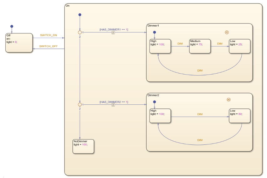
Variants in AUTOSAR Blockset components — AUTOSAR variants enable you to use variant blocks, variant parameters, and symbolic dimensions to implement AUTOSAR software components with variation points. A variation point in an AUTOSAR software component presents a choice between two or more variants. The exported ARXML code from the AUTOSAR software components contains definitions for variation point proxies and variation points. See Model AUTOSAR Variants (AUTOSAR Blockset).
This diagram illustrates the use of Variant Source and Variant Sink blocks to activate or deactivate AUTOSAR elements such as ports and runnables within a model. The Variant Source block passes the signal from
Runnable_Stepto trigger themyslfunc_sysfunction when the value of the variableAequals to1. Otherwise, the connection is disabled andmyslfunc_sysremains inactive.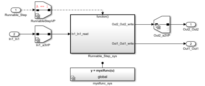
Variants in architecture models — Variant components enable you to represent multiple architectural implementations of a system component in a single model and switch between them using variant controls. For more information, see Design Insulin Infusion Pump Using Model-Based Systems Engineering (System Composer).
Note
If you have a Component (System Composer) block in your model and want to include multiple architectural configurations within it, use the
makeVariant(System Composer) function to convert the Component block into a Variant Component (System Composer) block. To manage the variant choices from external sources, convert the Component block to a Variant Assembly Component (System Composer) block using themakeVariantAssembly(System Composer) function.This diagram illustrates how the Variant Component block enables switching between different architectural implementations of sensors within the system. The Variant Component block, named
BGSensor, contains two variant choicesSensorAandSensorBeach representing a sensor from a different manufacturer. During simulation, the variant choice you select,SensorAorSensorB, becomes active.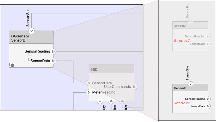
Variants in physical network — The Variant Connector (Simscape) block and the Variant Subsystem block in
labelmode allow you to define variations within a physical network in your model. You can activate or deactivate the variations using variant controls during simulation. For more information, see Using Variant Connectors to Implement Variations in Physical Networks (Simscape).This diagram demonstrates how primary and nonprimary Variant Connector blocks activate or deactivate the flow of current to specific components within an electrical circuit. The blocks in the bounded region formed by the primary Variant Connector block
VC1and nonprimary Variant Connector blockVC2are active when the value of the variableAis set to1. The blocks in the bounded region formed by the primary Variant Connector blockVC3and nonprimary Variant Connector blockVC4are active when the value of the variableBis set to1.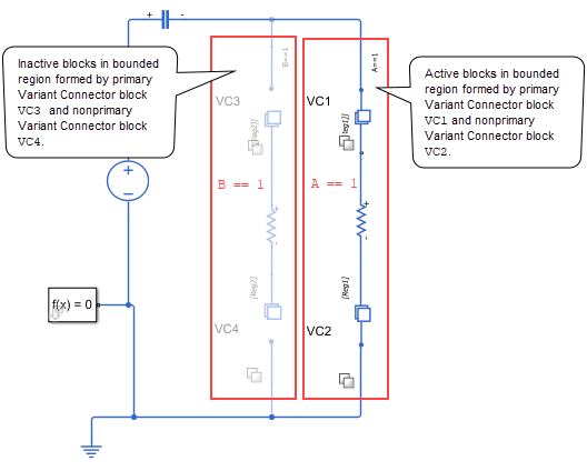
Case Study: Define and Manage Variants in Automotive Assembly Line
The Use Variants in Automotive Assembly Line Production example explains how variant concepts apply on the automotive assembly line to define, manage, and switch between different vehicle configurations. Additionally, it explains the role of Simulink Variant Manager in synchronizing these variants to minimize errors and discrepancies during operations.
Additional Resources for Working with Variants
The topics below provide additional resources for using variant control elements to define and activate design variations in a model and for using Simulink Variant Manager to synchronize variations within a variant configuration.

