simscape.multibody.Multibody Class
Namespace: simscape.multibody
Superclasses: simscape.multibody.Component
Description
Use an object of the simscape.multibody.Multibody class to construct a
multibody system. A Multibody object is a hierarchical container that can
have any type of component object, and each component object represents a part or a subsystem
of the multibody system. See simscape.multibody.Component for more information about different component
objects.
By default, a newly created Multibody object is empty. You can use the
methods of the Multibody object to construct a multibody system, prepare the
Multibody object for analyses, or create a corresponding Simulink® model. See the More About section for more information
about the Multibody class.
The simscape.multibody.Multibody class is a handle class.
Class Attributes
Sealed | true |
ConstructOnLoad | true |
HandleCompatible | true |
RestrictsSubclassing | true |
For information on class attributes, see Class Attributes.
Creation
Description
creates an
empty mb = simscape.multibody.Multibodysimscape.multibody.Multibody object.
Properties
Names of the component objects at the top level of the
simscape.multibody.Multibody object, returned as a string array.
Example: "Base_Bar"
Attributes:
GetAccess | public |
SetAccess | Restricts access |
NonCopyable | true |
Transient | true |
Gravitational acceleration in the multibody system, specified as a simscape.Value object that represents a 3-by-1 or 1-by-3 vector with a unit
of linear acceleration. The elements of the vector specify the gravity in the
x, y, and z directions of the
world frame. In a hierarchical simscape.multibody.Multibody object, the
Gravity property of the higher-level Multibody
object overrides the Gravity property of its contained
Multibody objects.
Attributes:
GetAccess | public |
SetAccess | public |
NonCopyable | true |
Transient | true |
Methods
addComponent | Add component object to Multibody object |
addConnector | Add connector to Multibody object |
compile | Compile Multibody object |
component | Extract component object from Multibody object |
componentPaths | Return paths of component objects in Multibody
object |
connect | Link two connectors in Multibody object |
connectVia | Link two connectors in Multibody object via intermediate
object |
jointPrimitivePaths | Return paths of joint primitives in Multibody object at all
hierarchical levels |
makeBlockDiagram | Create Simulink model from Multibody object |
removeConnector | Remove existing connector from Multibody object |
These methods specialize standard MATLAB® operators and functions for objects in this class.
disp | Prints the name and type of the connectors and components in the top
level of the |
Examples
This example shows how to assemble instances of a modularly designed link into a double pendulum. This double pendulum moves in the x-y plane of the world frame.
To avoid typing the namespace name for the classes, you can use the import function.
import simscape.Value simscape.op.* simscape.multibody.*;
Construct a Double Pendulum
Create a
simscape.multibody.Multibodyobject to construct the double pendulum. By default, a newly createdMultibodyobject is empty.
doublePendulum = Multibody
doublePendulum =
Multibody:
No connectors.
No components.
No connections.
Multibody with properties:
ComponentNames: [0×1 string]
Gravity: [0 0 -9.8066] (m/s^2)
DoVisualize: 1
FrameConnectors: [0×1 string]
Create two links by using the custom function described in the Link Creation Function section. To add the links to the
doublePendulumobject, you can use theaddComponentmethod. The upper link has a length of12cmand the red color. The lower link has a length of8cmand the blue color. The two links have rectangular shapes with the default density.
upperLength = Value(12,"cm"); lowerLength = Value(8,"cm"); addComponent(doublePendulum,"Upper_Link",link(upperLength,[1 0 0])); addComponent(doublePendulum,"Lower_Link",link(lowerLength,[0 0 1]));
Create two revolute joints by using the
simscape.multibody.RevoluteJointclass. You can use these joints to connect the upper and lower links.
joint = RevoluteJoint; addComponent(doublePendulum,"World_Upper_Joint",joint); addComponent(doublePendulum,"Upper_Lower_Joint",joint);
Add the world frame to the
doublePendulumobject and connect the positive end of the upper link to the world frame via the revolute joint namedWorld_Upper_Joint. To make the connection, you can use theconnectViafunction.
addComponent(doublePendulum,"World",WorldFrame); connectVia(doublePendulum,"World_Upper_Joint","World/W","Upper_Link/pos_end");
Connect the positive end of the lower link to the negative end of the upper link via the revolute joint named
Upper_Lower_Joint.
connectVia(doublePendulum,"Upper_Lower_Joint","Upper_Link/neg_end","Lower_Link/pos_end");
Reorient the gravity from negative z-direction to the negative y-direction because the double pendulum moves only on the x-y plane of the world frame.
doublePendulum.Gravity = circshift(doublePendulum.Gravity,-1);
To specify the initial position for the upper link, you can use a simscape.op.OperatingPoint object and a simscape.op.Target.
op = OperatingPoint; op("World_Upper_Joint/Rz/q") = Target(60,"deg","High");
To see the components in the doublePendulum object, you can type:
doublePendulum
doublePendulum =
Multibody:
No connectors.
Components:
Name Type
___________________ ______________
"Lower_Link" Rigid Body
"Upper_Link" Rigid Body
"Upper_Lower_Joint" Revolute Joint
"World" World Frame
"World_Upper_Joint" Revolute Joint
Connections:
Connector 1 Connector 2
____________________ _____________________
"Lower_Link/pos_end" "Upper_Lower_Joint/F"
"Upper_Link/neg_end" "Upper_Lower_Joint/B"
"Upper_Link/pos_end" "World_Upper_Joint/F"
"World/W" "World_Upper_Joint/B"
Multibody with properties:
ComponentNames: [5×1 string]
Gravity: [0 -9.8066 0] (m/s^2)
DoVisualize: 1
FrameConnectors: [0×1 string]
Link Creation Function
You can use this function to create a link with specific length and color. Frames at the ends of the link are always exposed as connectors for connections to joints. See more information about creating a link, see Simple Link.
function link = link(length,color) import simscape.Value simscape.multibody.*; link = RigidBody; offset = length/2; addFrame(link,"neg_end","reference",RigidTransform(StandardAxisTranslation(offset,Axis.NegX))); addFrame(link,"pos_end","reference",RigidTransform(StandardAxisTranslation(offset,Axis.PosX))); % Add component solid = Solid(GeneralExtrusion(roundedRect(length,Value(2,"cm")),Value(1,"cm")),... UniformDensity,SimpleVisualProperties(color)); addComponent(link,"Body","reference",solid); % Connectors addConnector(link,"neg_end"); addConnector(link,"pos_end"); end function xs = roundedRect(length,width) % Return the cross section of a rectangle with rounded ends angles = (-90:10:+90)'*pi/180; semi = width/2*[cos(angles) sin(angles)]+repmat([length/2 0],size(angles)); xs = [semi;-semi]; end
More About
By default, a newly created simscape.multibody.Multibody object is empty
and has zero connectors. To construct a multibody system, use the addComponent method
to add objects to the Multibody object, then connect the objects using the
connect or connectVia method.
Each object represents a part or a subsystem of the multibody system.
To manage the complexity of a large multibody system, you can use several
Multibody objects to model the subsystems of a system. The image shows an
example of a large multibody system, Robot.

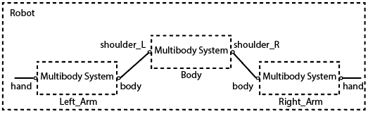
Note that you must completely construct a Multibody object before
adding it to a system. For example, in this example, you need to add the connectors
hand and body to the Left_Arm
object before adding it to the Robot object. To add the connectors, use the
addConnector
method.
To establish mechanical relationships between the three subsystems in the
Robot system, connect the Body,
Left_Arm, Right_Arm objects, as shown in the image, by
using the connect or connectVia
method.
To analyze a multibody system, you need to successfully compile the
simscape.multibody.Multibody object of the system by using the compile method. The
compilation performs a thorough error checking for a Multibody object. If any
error occurs, the compile method shows the problem. For example, if a
Multibody object contains joint objects or simscape.multibody.RigidTransform objects that do not connect to the main
structure of the Multibody object, the compilation fails. See compile and simscape.multibody.CompiledMultibody for more information about compilation and
analysis methods.
To use the capabilities in Simscape Multibody that you cannot do programmatically, such
as simulating a multibody system, create a Simulink model from a
simscape.multibody.Multibody object by using the makeBlockDiagram
method.
When you construct a multibody system programmatically, Simscape Multibody has a
different approach to specify the state of the joint primitives in the system. Instead of
specifying the state through joint targets in joint blocks, the programmatic way uses the
simscape.op.OperatingPoint object to specify state targets for joint primitives.
Therefore, when you create a Simulink model from a Multibody object, the
makeBlockDiagram method must have both the OperatingPoint
object that specifies the joint states of the system and the Multibody object
that defines the structure of the system. The makeBlockDiagram method uses
the data in the OperatingPoint object to populate the joint target parameters
for the joint blocks of the created Simulink model. Note that if the
OperatingPoint object targets some joint primitives that do not exist in
the Multibody object, those targets are ignored.
Tip
When setting up the targets of joint primitives, use the jointPrimitivePaths
method to display the paths of primitives in Multibody object.
After you create the Simulink model from a Multibody object, the model
can be modified just like general Simulink models. However, a best practice is to avoid
making changes in the Simulink model that you can make in the Multibody
object. Make the changes in the code that generates the Multibody object,
re-generate the object, and then re-create the Simulink model. This process allows you to
keep the code as the main source for the model. However, some capabilities are not supported
in the programmatic way, and so must be done in Simulink model. For example, you can specify
input signals only in the Simulink model.
Version History
Introduced in R2022a
MATLAB Command
You clicked a link that corresponds to this MATLAB command:
Run the command by entering it in the MATLAB Command Window. Web browsers do not support MATLAB commands.
Sélectionner un site web
Choisissez un site web pour accéder au contenu traduit dans votre langue (lorsqu'il est disponible) et voir les événements et les offres locales. D’après votre position, nous vous recommandons de sélectionner la région suivante : .
Vous pouvez également sélectionner un site web dans la liste suivante :
Comment optimiser les performances du site
Pour optimiser les performances du site, sélectionnez la région Chine (en chinois ou en anglais). Les sites de MathWorks pour les autres pays ne sont pas optimisés pour les visites provenant de votre région.
Amériques
- América Latina (Español)
- Canada (English)
- United States (English)
Europe
- Belgium (English)
- Denmark (English)
- Deutschland (Deutsch)
- España (Español)
- Finland (English)
- France (Français)
- Ireland (English)
- Italia (Italiano)
- Luxembourg (English)
- Netherlands (English)
- Norway (English)
- Österreich (Deutsch)
- Portugal (English)
- Sweden (English)
- Switzerland
- United Kingdom (English)