Modeling Contact Force Between Two Solids
When modeling solid blocks in contact with each other, contact forces play an important role
in how the solid blocks behave. Both the normal force,
fn, and the frictional force,
ff, can cause the dynamic
behaviors of a multibody model to change. For more information about multibody
dynamics simulation, see Multibody Dynamics. Contact
forces come into play in many different modeling situations, such as:
Package conveyors
Robotic movement
Race car dynamics
The Spatial Contact Force block models forces between base and follower frame solid bodies. When the two solid blocks are connected, the Spatial Contact Force block applies equal and opposite forces along a common contact plane. These forces conform to Newton's Third Law. The normal force is applied based on the penetration depth and the penetration velocity. If applied, the frictional force is based on the normal force and the relative velocities at the point of contact.

Simscape™ Multibody™ uses a penalty method for modeling contact between bodies, which allows the bodies to penetrate a small amount. Contact forces in the normal direction are computed using a spring-damper force law: the deeper the penetration and the greater the relative velocity in the penetration direction, the greater the normal contact forces.
Spatial Contact Force Block Forces
The Spatial Contact Force block properties are divided into three expandable nodes: Normal Force, Frictional Force, and Sensing. Set these properties when using the Spatial Contact Force block to model the contact forces between two solid bodies.
For more information about these properties, see Spatial Contact Force.
Normal Force
Parameters in the Normal Force section are used to determine the normal force, fn, that the two solid bodies exert on each other. You can specify the Stiffness, Damping, and Transition Region Width.
Frictional Force
Parameters in the Frictional Force section are used to determine the frictional force, ff, that the two solid bodies exert on each other. If you set Method to Smooth Stick-Slip, then you can specify the Coefficient of Static Friction, Coefficient of Dynamic Friction, and Critical Velocity. These options are not available when the Method is set to None.
Sensing
Besides modeling contact between two solid blocks, you can also use the Spatial Contact Force block to sense:
Separation Distance—The distance between two solid bodies
Normal Force—The normal force exerted by each solid body on the other.
Frictional Force Magnitude—The frictional force exerted by each solid body on the other.
To enable these options, open the Spatial Contact Force block properties. Under Sensing, select the properties that you want the block to sense. For each property, a port is exposed on the block. Connect these ports to a viewer of your choice.

Connect to Solid Blocks
The Spatial Contact Force block does not inherently know information about the two connecting solid bodies. In the solid block parameters, enable the Export: Entire Geometry option.
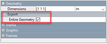
Once this option is enabled a new geometry port, G, appears on your solid block.

Connect the geometry port to the base or follower port on the Spatial Contact Force block. Follow the same steps for your other solid block and connect it to the remaining port. To learn more about base and follower frames, see Selecting a Measurement Frame.
Considerations for Contact Modeling
Compared to modeling the mechanical relationships in a multibody system, modeling contact presents more choices, and the chosen methods can impact simulation speed, accuracy, and model maintainability. Simscape Multibody provides basic contact modeling constructs, but there are many ways to use them.
Solver Parameters
The computed normal contact forces are continuous functions of penetration depth and penetration velocity. Simscape Multibody computes these normal forces by reducing the spring and damper forces when the depth is less than the Transition Region Width. Increasing the Transition Region Width reduces the sharpness of the contact force, making the system easier for the solver to advance, but allowing greater amounts of penetration. Decreasing the Transition Region Width gives the contact forces a sharper profile, closer to idealized rigid-body contact. However, decreasing the Transition Region Width may also degrade solver performance.
Setting the maximum step size to 1e-3 seconds or lower improves accuracy in many models. Reducing the relative solver tolerance can produce a similar effect. However, reducing the step size also reduces the simulation speed.
Explicit solvers, such as ode45, are usually better for systems with many rapid collisions or contact changes. Implicit solvers may struggle under such circumstances. If the contact changes are infrequent and more stable, implicit solvers may offer a speed advantage due to their ability to handle the stiffness introduced by the contact forces.
Limit Penetration Depth
The separation distance between two solid blocks is positive when the two geometries are not in contact, zero when they are touching, and negative when there is nontrivial penetration between the geometries. When the separation distance is negative, its magnitude is also known as the penetration depth. Penetration depth is a continuous function of the positions and orientations of the geometries.
Simscape Multibody uses geometry analysis algorithms that are tuned for small contact-modeling applications. Some of the algorithms assume that the penetration depth is small compared to the size of the geometries. If this is not the case, the computed (negative) separation distances may only be approximate, or may exhibit discontinuities, and the resulting contact forces may be erratic. For best results, limit penetration depth in your model.
See Also
Spatial Contact Force | Brick Solid | Cylindrical Solid | Spherical Solid