PTC Thermistor
Positive temperature coefficient (PTC) thermistor
Libraries:
Simscape /
Electrical /
Sensors & Transducers
Description
The PTC thermistor block models a positive temperature coefficient (PTC) thermistor. To model a switching PTC thermistor or a resistance temperature detector (RTD), use this block. To model a non-switching linear PTC thermistor, use the Thermal Resistor block.
The thermal behavior of the block uses the equation
where:
Q is the net heat flow into the A port.
Kd is the Dissipation factor parameter value.
tc is the Thermal time constant parameter value.
dT/dt is the rate of change of temperature with respect to time.
I is the current.
R is the resistance.
Note
You must not connect the PTC Thermistor block to an ideal current source. This arrangement creates a positive feedback loop that results in thermal runaway because:
Increasing the temperature increases the resistance
Increasing the resistance with an ideal current source increases the voltage
Increasing the voltage increases the dissipated power
Increasing the dissipated power increases the temperature, which closes the loop
Temperature Operating Limits
Since R2024a
If you set the Thermistor parameterization type parameter to
Switching Thermistor, you can choose whether to
specify the range of operating temperatures by using the Enable
temperature operating limits parameter. If you set the
Thermistor parameterization type parameter to
RTD (Callendar - Van Dusen coefficients), you must
specify the range of operating temperatures.
Specify the lower and upper temperature operating limits by setting the Minimum operating temperature and Maximum operating temperature parameters, respectively. Find these values on a datasheet. If the temperature falls outside of the operating limits:
If you set Reporting if operating limits exceeded to
Warn, Simulink® displays a warning and the simulation continues.If you set Reporting if operating limits exceeded to
Error, Simulink displays an error and terminates the simulation.
Switching Thermistor
To model a switching PTC thermistor, set the Thermistor parameterization
type parameter to Switching Thermistor.
This type of thermistor has a decreasing resistance with increasing temperature up
to the Curie temperature Tc. Above the
Curie temperature, the resistance increases rapidly with increasing temperature. The
region to the right of Tc in this figure
is called the PTC regime.
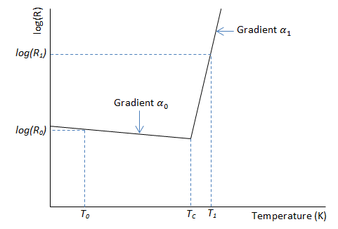
This equation defines the resistance R at temperature T,
where:
R0 is the resistance at the nominal temperature.
R1 is the resistance at the reference temperature.
α0 is the temperature coefficient at the nominal temperature.
α1 is the temperature coefficient at the reference temperature.
T0 is the nominal temperature at which you quote the nominal resistance, usually room temperature. T0 must be less than the Curie temperature.
T1 is the reference temperature at which you quote the reference resistance. T1 must be in the PTC regime.
Resistance Temperature Detector
Since R2024a
To model an RTD, set the Thermistor parameterization type to
RTD (Callendar - Van Dusen coefficients). The
Callendar–Van Dusen equation defines the resistance R at
temperature T. This equation uses T measured
in degC,
where:
R0 is the resistance at the nominal temperature of 0 degC.
A, B, and C are the Callendar–Van Dusen coefficients.
You can find these coefficients on a datasheet. The default parameter values that the block uses are typical for platinum RTDs. The R-T characteristic is approximately linear within the range of operating temperatures so choose values of B and C that are several orders of magnitude smaller than A.
Simulink displays a warning if the resistance does not increase monotonically
over the range of operating temperatures. If you set the Reporting if
operating limits exceeded parameter to
Warn and the temperature falls outside of the
operating range, the block uses linear extrapolation to calculate the resistance
with respect to temperature.
Variables
To set the priority and initial target values for the block variables before simulation, use the Initial Targets section in the block dialog box or Property Inspector. For more information, see Set Priority and Initial Target for Block Variables.
Use nominal values to specify the expected magnitude of a variable in a model. Using system scaling based on nominal values increases the simulation robustness. Nominal values can come from different sources. One of these sources is the Nominal Values section in the block dialog box or Property Inspector. For more information, see System Scaling by Nominal Values.