Author Sequence Diagrams Interactively
Sequence diagrams describe the operational behavior of an architectural system. You can use sequence diagrams in early phases of system design to describe expected model behaviors as interactions. You can represent elements of an interaction using lifelines, messages, fragments, and operands in sequence diagrams. To learn how to create a sequence diagram, see Create New Sequence Diagram.
This topic shows you how to author a sequence diagram to describe the scenario of a pedestrian crossing the street at an intersection with traffic lights. You will learn how to represent:
Instances of components as participants of the interaction using lifelines.
Signal-based and message-based communication with messages.
More complex patterns of interaction such as looping and alternatives using fragments.
Constraints on time between message events using duration constraints.
Open Sequence Diagram for Traffic Light Architecture
This example contains sequence diagrams that describe pedestrians crossing an intersection against a traffic light. The model describes these steps:
The traffic signal cycles from red to green to yellow.
When the pedestrian crossing button is pressed, if the traffic signal is green, the traffic signal transitions from yellow to red for a limited time.
The pedestrians cross while the walk signal is active.
Open the architecture model.
model = systemcomposer.openModel('TLExample');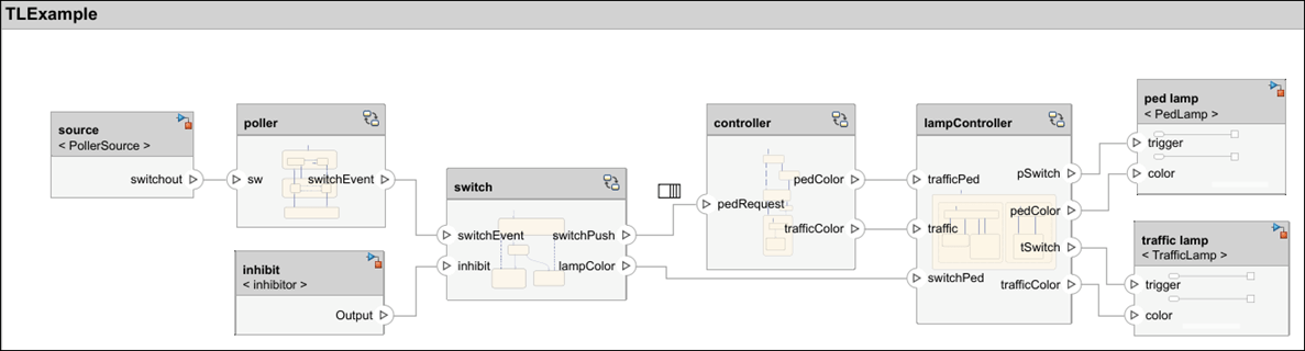
Open the Inhibit sequence diagram in the Architecture Views Gallery.
interaction = model.getInteraction("Inhibit");
open(interaction)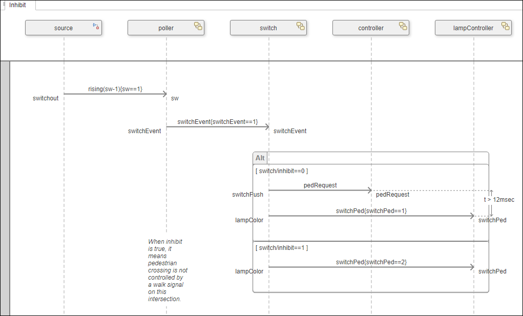
Describe Interactions with Lifelines and Messages
Each component from your architecture model can be represented in a sequence diagram with a lifeline.
Add Lifelines
To begin specifying component interactions, add lifelines to your sequence diagram. Select Component > Add Lifeline. From the list that appears, select a component or child component. Alternatively, from the Model Components pane of the Architecture Views Gallery, click and drag a component into the sequence diagram.
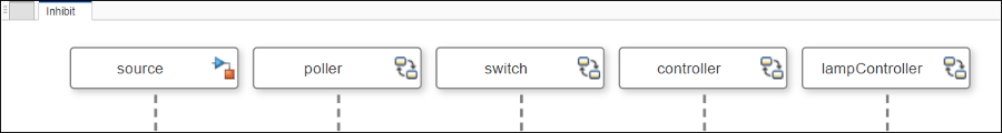
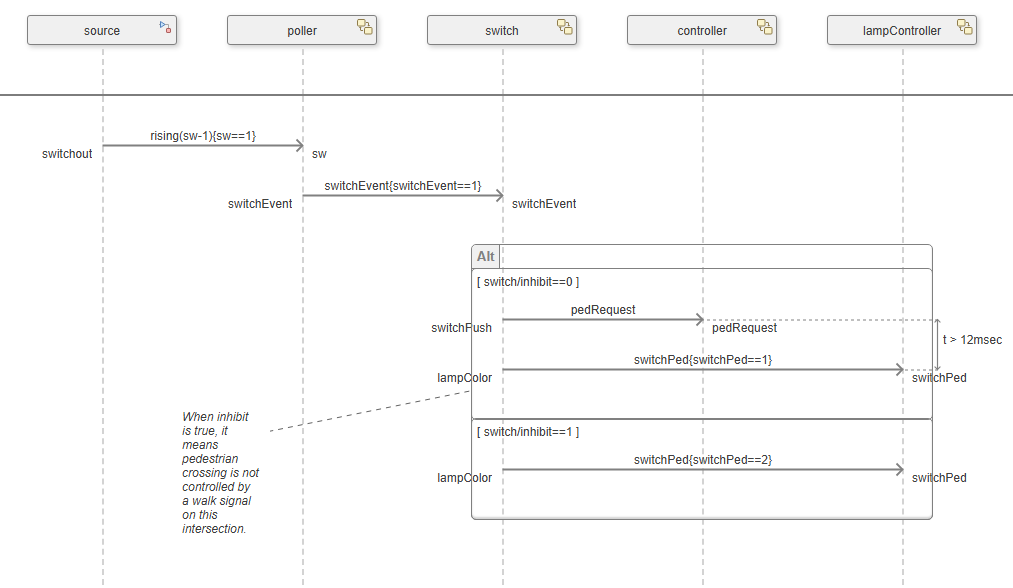
The lifelines of the Inhibit sequence diagram are instances of
components from the TLExample architecture.
source– Detects when the pedestrian presses the crossing buttonpoller– Checks if the pedestrian crossing button has been pressedswitch– Processes the signalcontroller– Determines which color the pedestrian lamp and traffic light should displaylampController– Changes the traffic light colors
Add Messages
Components of your architecture are connected through ports and connectors that represent an exchange of information. Similarly, in sequence diagrams, lifelines are connected through message ends and messages. Each message describes a pair of events. A signal-based message describes signal write and signal read events. A message-based message describes message send and message receive events.
To add messages between lifelines, click and drag the vertical dotted line that connects one lifeline to another.
To represent the destination port of the message, in the To box, select or type a port name.
To represent the source port of the message, in the From box, select or type a port name.
Tip
Components of your architecture may be connected to root architecture ports which represent an exchange of information outside the boundary of the architecture. In sequence diagrams, you can connect gates to lifelines. A gate represents the root of an architectural hierarchy. A gate allows you to describe the exchange of messages between the architecture and its environment.
To add a message from a lifeline to a gate, click and drag the vertical dotted lines from one lifeline to the gutter region.
In the Inhibit sequence diagram, the source
and poller lifelines exchange a message represented by a solid
line with an open arrow.

Use message labels on messages to define the expected conditions for this information exchange. Edit a message label by clicking the message and double-clicking the empty message label that appears.
A message label has a trigger, an optional guard, and an
optional constraint in the form of trigger[guard]{constraint}.
trigger represents the identifying event for this message.
guard represents an additional condition to determine whether the message
occurs. constraint is an expression that is expected to be true when this
message occurs.
In signal events, the trigger follows this format:
direction(signal [+|-]
                    value)
, which specifies a triggering edge with a direction and an expression. The direction can be:Rising — The edge expression is rising from strictly below zero to a value equal to or greater than zero.
Falling — The edge expression is falling from strictly above zero.
Crossing — The edge expression either rising or falling past zero.
In message events, the trigger is in the format
port, which specifies the name of the input message port and represents the arrival of a message.A guard in square brackets on the message label is a MATLAB® Boolean expression that is an additional condition to determine whether the message occurs. Evaluation of the guard only occurs once the software detects a valid trigger. During execution, the sequence diagram waits to proceed to the next message until the guard expression evaluates to true.
A constraint in curly brackets on the message label is a MATLAB Boolean expression that specifies an expected value of inputs to the destination lifeline. During execution, the evaluation of the constraint determines whether the sequence diagram shows a pass or fail for that message. If a constraint expression is not specified, the evaluation of the trigger determines whether the sequence diagram shows a pass or fail for that message.
Signal-Based Communication. The message between the source and
poller lifelines defines this condition:
rising(sw-1){sw==1}. The trigger of the message,
rising(sw-1), indicates that the message is triggered
when the sw signal rises from below 1 to a
value of 1 or above. The constraint of the message,
{sw==1}, indicates that the message is invalid when
sw is not equal to 1.
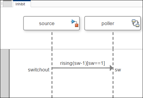
In this example, when the sw signal becomes
1, the pedestrian crossing button has been pressed, and
the software recognizes a message to the poller
lifeline.
Message-Based Communication. The message between the poller and
switch lifelines defines this condition:
switchEvent[switchEvent==1]. The trigger of the message,
switchEvent, indicates that the message is triggered by
the arrival of a message through the switchEvent port. The
guard of the message, [switchEvent==1], indicates that the
value at switchEvent must be 1 for the
message to occur.
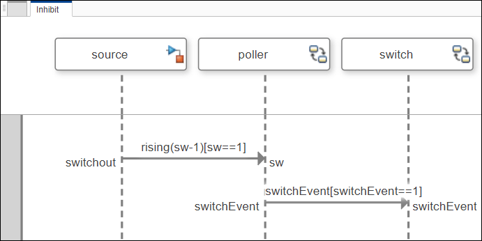
In this example, the message occurs when the switchEvent
message event is received and its value is 1.
Model Complex Interactions with Fragments and Operands
A fragment encloses a group of lifelines and messages within an interaction to allow for the specification of more complex patterns of interaction. A fragment defines the type of ordering logic such as looping and alternatives. Fragments can have one or more operands. Use fragments and operands to add conditional behavior to a group of messages.
To access the menu of fragments:
To select two messages, click and drag.
To access the action bar, pause on the ellipsis (...) that appears.

A list of fragments appears:
Alternative (Alt Fragment)
Optional (Opt Fragment)
Loop (Loop Fragment)
Weak sequencing (Seq Fragment)
Strict sequencing (Strict Fragment)
Parallel (Par Fragment)
For more information, see Model Complex Interactions Using Fragments in Sequence Diagrams.
Add Alternative Fragments
In the Inhibit sequence diagram, an Alt Fragment
represents multiple mutually exclusive conditions under which different sets of
messages are expected to occur, similar to an IF-ELSEIF-THEN
clause in a software program.

The alt fragment contains two operands and the messages inside an operand can only be executed if the constraint condition is true. The conditions of the operands in the alt fragment are:
switch/inhibit==0This operand works like an
ifcondition. When theinhibitflag of theswitchis0, the messages within this operand will be executed.This operand represents the scenario where pedestrian crossing is controlled by a walk signal.
When the
inhibitflag is0, the software recognizes the message to thecontrollerlifeline and validates thepedRequestmessage.Then, when the
switchPedmessage value is1, thelampControllerlifeline allows the pedestrian to cross.
switch/inhibit==1This operand works like an
elseifcondition. When theinhibitflag of theswitchis1, the message executes.This operand represents the scenario where pedestrian crossing is not controlled by a walk signal.
When the
inhibitflag is1, theswitchbypasses thecontrollerlifeline, so pedestrian crossing does not affect the traffic signal.When the
switchPedmessage value is2, the pedestrian may proceed with caution, as indicated by a yellow walk signal.
Add Loop Fragments
In the PedestrianCross sequence diagram, a Loop Fragment
represents a repeatable operand that repeats the sequence of messages until it
reaches the maximum number of iterations, similar to a FOR loop
in a software program.
The loop fragment contains one operand and the messages inside the operand execute if the first event is valid. A loop fragment with no specified upper or lower bounds repeats a certain number of times according to either the simulation time or the lower and upper bounds of the architecture model.
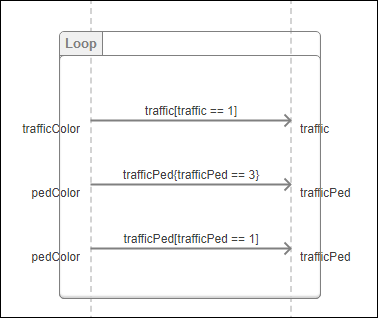
As a loop fragment with no bounds, this fragment repeats a number of times based on the simulation time. This interaction represents the default sequence of lights.
traffic[traffic == 1]When the
trafficColorport of thecontrollerlifeline receives a message and thetrafficvalue is1, the software recognizes and validates the message to thelampControllerlifeline.The first message in the loop fragment indicates that the traffic light color is red, which is represented by the
[traffic == 1]guard.trafficPed{trafficPed == 3}When the
pedColorport of thecontrollerlifeline receives a message and thetrafficPedvalue is3, the software recognizes and validates the message to thelampControllerlifeline.The second message in the loop fragment indicates that the pedestrian walk signal is green, which is represented by the
{trafficPed == 3}constraint.trafficPed[trafficPed == 1]When the
pedColorport of thecontrollerlifeline receives a message and thetrafficPedvalue is1, the software recognizes and validates the message to thelampControllerlifeline.The third message in the loop fragment indicates that the pedestrian walk signal is red, which is represented by the
[trafficPed ==
                                1]
guard.
Send and Receive Sequence Diagram Messages by Same Lifeline
Since R2026a
Self-messages (feedback loops) in sequence diagrams represent a connection from one component back into that component.
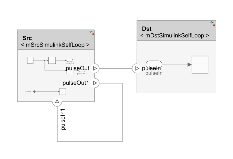
Self messages are supported in sequence diagrams for authoring and simulation. You can send and receive a message by the same lifeline.
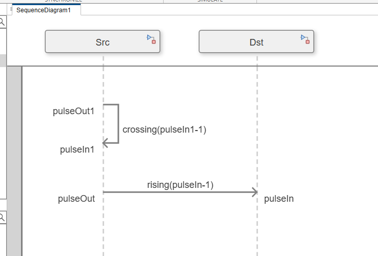
The crossing(pulseIn1-1) message is created between two message
ends around the same Src lifeline. This self message shows that when
the pulseIn1 signal crosses 1, the sequence
diagram is valid.
Specify Timing Constraints Between Message Events with Duration Constraints
Since R2025a
A duration constraint defines a constraint on elapsed time between a start and an end occurrence. A duration constraint has a start occurrence, an end occurrence, and an expression. The start and end occurrences represent event occurrences, such as message ends, and the expression defines limits on the duration of time between those occurrences.
To add duration constraints to your sequence diagrams, press Shift and select two message events with your pointer. You can select two message events from:
Different messages to define a constraint on duration of time between the message events
A single message to define a constraint on duration of time between the start and end of a message
Edit a duration constraint by double-clicking the expression.
Duration Constraint Timing Syntax
Use relational operators like "less than" and "greater than" to express a constraint on the duration between two occurrences.
An expression of a duration constraint contains:
A keyword to represent the duration observation. Use:
torduration.A relational operator. Use:
>,<,>=, or<=.A time value.
A unit of time. Use:
sec,msec, orusec.
These examples show duration constraint expressions.
t < 15sec, checks whether if the duration observation between the two message events is less than15sec.1usec < duration <= 3usec, checks whether the duration observation between the two message events is greater than1usecand less than or equal to3usec.5msec >= t > 10msec, checks whether the duration observation between the two message events is less than or equal to5msecor greater than10msec.
In the Inhibit sequence diagram, a duration constraint with an
expression t > 12msec is between two message events in the alt
fragment.
The duration constraint indicates that the duration observation between the two
message events is expected to be greater than 12msec.
In the PedestrianCross sequence diagram, a duration constraint
with an expression 1sec < t < 3sec is between two message
events of the same message.

The duration constraint indicates that the duration observation between the start
and end of the message is expected to be greater than 1sec and
less than 3sec.
Annotate Sequence Diagrams with Annotations
An annotation describes the elements of a sequence diagram. Use annotations to provide detailed explanations of elements or workflows captured by sequence diagrams.
To create an annotation, double-click the canvas. In the text box that appears, enter the annotation text. In this sequence diagram, an annotation beside the alt fragment provides a brief meaning of the fragment.
You can associate annotations in sequence diagrams by linking annotations to messages, message ends, composite fragments, and lifeline tails. Click and drag a line from the annotation to the sequence diagram element. When the sequence diagram element moves, the annotation follows. Resize annotations by clicking and dragging the corners of the annotation.
Edit Layout of Sequence Diagrams
Since R2025a
To enhance readability, you can edit the layout of your sequence diagrams.
Reposition lifelines, fragments, and messages – Click and drag elements to adjust their horizontal and vertical positions relative to other elements.
Resize lifelines – Click the edge of a lifeline and drag your cursor.
To adjust the size of a lifeline based on the content within the element, you can right-click a lifeline and select the Fit to Content option.
Reposition duration constraints – Click and drag duration constraints horizontally to adjust their position.
Add operands – Right-click within a fragment and select one of these options to modify operands:
Insert Operand Before,Insert Operand After, orDelete.
Tip
When you reposition elements, you can accelerate the movement by pressing Ctrl while dragging the element.