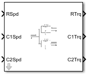
Split Torsional Compliance
Split torsional coupler
Libraries:
Powertrain Blockset /
Drivetrain /
Couplings
Vehicle Dynamics Blockset /
Powertrain /
Drivetrain /
Couplings
Description
The Split Torsional Compliance block implements parallel spring-damper coupling between shafts. You can specify the type of coupling by selecting one of the Coupling Configuration parameters:
Shaft split— Single input shaft coupled to two output shaftsShaft merge— Two input shafts coupled to a single output shaft
In fuel economy and emissions studies, you can use the Split Torsional
Compliance block to model mechanical rotational compliance between common
driveline elements such as motors, planetary gears, and clutches. For example, use the
Shaft split configuration to couple a motor and two
planetary gear sets. Use the Shaft merge configuration to
couple a dual clutch transmission to an output shaft.
Shaft Split
For the Shaft split configuration, the block implements
this schematic and equations.

To account for frequency-dependent damping, both damping terms incorporate a low-pass filter.
The equations use these variables.
| Tin | Resulting applied input reaction torque |
| ωin | Input shaft rotational velocity |
| T1out | Resulting applied torque to first output shaft |
| ω1out | First output shaft rotational velocity |
| T2out | Resulting applied torque to second output shaft |
| ω2out | Second output shaft rotational velocity |
| θ1, θ2 | First, second shaft rotation, respectively |
| b1, b2 | First, second shaft viscous damping, respectively |
| k1, k2 | First, second shaft torsional stiffness, respectively |
Shaft Merge
For the Shaft merge configuration, the block implements
this schematic and equations.
To account for frequency-dependent damping, both damping terms incorporate a low-pass filter.
The equations use these variables.
| Tout | Resulting applied output torque |
| ωout | Output shaft rotational velocity |
| T1in | Resulting reaction torque to first input shaft |
| ω1in | First input shaft rotational velocity |
| T2in | Resulting reaction torque to second input shaft |
| ω2in | Second input shaft rotational velocity |
| θ1, θ2 | First, second shaft rotation, respectively |
| b1, b2 | First, second shaft viscous damping, respectively |
| k1, k2 | First, second shaft torsional stiffness, respectively |
Power Accounting
For the power accounting, the block implements these equations.
| Bus Signal | Description | Variable | Equations | ||
|---|---|---|---|---|---|
|
|
| For the | PTR | |
PwrC1 | For the | PTC1 | |||
PwrC2 | For the | PTC2 | |||
| For the | PTC | |||
PwrR1 | For the | PTR1 | |||
PwrR2 | For the | PTR2 | |||
|
| PwrDampLoss | Mechanical damping loss | Pd | ||
|
| PwrStoredShft | Rate change in spring energy | Ps | ||
The equations use these variables.
| TR | Shaft R torque |
| TC | Shaft C torque |
| ωR | Shaft R angular velocity |
| ωC | Shaft C angular velocity |
| θ | Coupled shaft rotation |
| k | Shaft torsional stiffness |
| b | Rotational viscous damping |
| Pt | Total mechanical power |
| Pd | Power loss due to damping |
| Ps | Rate change of stored spring energy |
Ports
Input
Output
Parameters
Extended Capabilities
Version History
Introduced in R2017b
See Also
Rotational Inertia | Torsional Compliance | Two-Way Connection