Main Content

Torsional Compliance

Parallel spring-damper

  • Torsional Compliance block

Libraries:
Powertrain Blockset / Drivetrain / Couplings
Vehicle Dynamics Blockset / Powertrain / Drivetrain / Couplings

Description

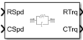
The Torsional Compliance block implements a parallel spring-damper to couple two rotating driveshafts. The block uses the driveshaft angular velocities, torsional stiffness, and torsional damping to determine the torques.

TR=(ωRωC)bθkTC=(ωRωC)b+θkθ˙=(ωRωC)

Power Accounting

For the power accounting, the block implements these equations.

Bus Signal DescriptionVariableEquations

PwrInfo

PwrTrnsfrd — Power transferred between blocks

  • Positive signals indicate flow into block

  • Negative signals indicate flow out of block

PwrR

Mechanical power from driveshaft R

PTR

PTR= TRωR

PwrC

Mechanical power from driveshaft C

PTC

PTC= Tcωc

PwrNotTrnsfrd — Power crossing the block boundary, but not transferred

  • Positive signals indicate an input

  • Negative signals indicate a loss

PwrDampLoss

Mechanical damping loss

Pd

Pd=b|θ˙|2

PwrStored — Stored energy rate of change

  • Positive signals indicate an increase

  • Negative signals indicate a decrease

PwrStoredShft

Rate change in spring energy

PS

Ps=θkθ˙

The equations use these variables.

TR

Driveshaft R torque

TC

Driveshaft C torque

ωR

Driveshaft R angular velocity

ωC

Driveshaft C angular velocity

θ

Coupled driveshaft rotation

k

Driveshaft torsional stiffness

b

Rotational viscous damping

Pd

Power loss due to damping

Ps

Rate change of stored spring energy

Ports

Input

expand all

Input driveshaft angular velocity, in rad/s.

Dependencies

To enable this port, for Port Configuration, select Simulink.

Output driveshaft angular velocity, in rad/s.

Dependencies

To enable this port, for Port Configuration, select Simulink.

Angular velocity in rad/s. Torque is in N·m.

Dependencies

To enable this port, for Port Configuration, select Two-way connection.

Output

expand all

Bus signal containing these block calculations.

SignalDescriptionVariableUnits
Trq

R

Input driveshaft torque

TRN·m

C

Output driveshaft torque

TCN·m

Damp

Damping torque

Ts=bθ˙

N·m

Spring

Spring torque

Td = kθ

N·m

Spd

R

Input driveshaft angular velocity

ωRrad/s

C

Output driveshaft angular velocity

ωCrad/s

deltadot

Difference in input and output driveshaft angular velocity

θ˙

rad/s
PwrInfo

PwrTrnsfrd

PwrR

Mechanical power from driveshaft R

PTR

W
PwrC

Mechanical power from driveshaft C

PTC

W

PwrNotTrnsfrd

PwrDampLoss

Power loss due to damping

Pd

W

PwrStored

PwrStoredShft

Rate change of stored internal kinetic energy

Ps

W

Dependencies

To enable this port, select Output Info bus.

Input drive shaft torque, in N·m.

Dependencies

To enable this port, for Port Configuration, select Simulink.

Applied output driveshaft torque, in N·m.

Dependencies

To enable this port, for Port Configuration, select Simulink.

Angular velocity in rad/s. Torque is in N·m.

Dependencies

To enable this port, for Port Configuration, select Two-way connection.

Parameters

expand all

Block Options

Specify the port configuration.

Dependencies

Specifying Simulink creates these ports:

  • RSpd

  • CSpd

  • RTrq

  • CTrq

Specifying Two-way connection creates these ports:

  • R

  • C

Select to create the Info output port.

Torsional stiffness, in N·m/rad.

Torsional damping, in N·m· s/rad.

Initial deflection, in rad.

Initial velocity difference, in rad/s.

Damping cut-off frequency, in rad/s.

Extended Capabilities

C/C++ Code Generation
Generate C and C++ code using Simulink® Coder™.

Version History

Introduced in R2017a