OFDM Equalizer
Equalize OFDM data using channel estimates
Libraries:
Wireless HDL Toolbox /
Modulation
Description
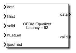
The OFDM Equalizer block equalizes the OFDM data using channel estimates. The block supports zero-forcing (ZF) and minimum mean squared error (MMSE) algorithms for channel equalization in the frequency domain. The block accepts data symbols, estimated channel (hEst), and the estimated channel length per symbol (hEstLen) data ports and valid and loadhEst control ports. The block outputs an equalized data port and a valid control port.
You can use this block to equalize channel effects in different communications standards, such as long term evolution (LTE) [1], 5G new radio (NR) standard TS 38.212 [2], and wireless local area network (WLAN) [3].
The block provides an interface and architecture suitable for HDL code generation and hardware deployment.
Examples

Equalize OFDM Data Using Channel Estimates
Equalize OFDM data subcarriers using channel estimates.
Ports
Input
Output
Parameters
Algorithms
The OFDM Equalizer block supports ZF and MMSE algorithms for channel equalization in the frequency domain. The block stores the estimated channel information to equalize the OFDM symbols and generates the equalized output using these algorithms.
The OFDM Equalizer block operation sequence is implemented using these subsystem blocks: Sample and control information, Store and retrieve channel estimates, and ZF/MMSE equalization. This figure shows these blocks.
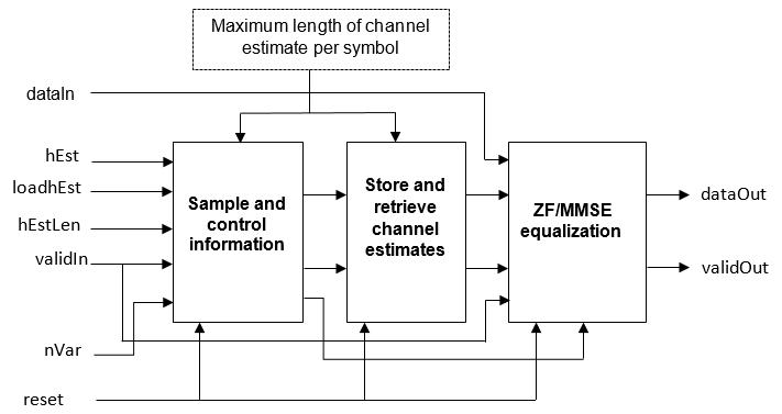
The Sample and control information block samples and validates the
hEstLen input based on the loadhEst input signal,
validates the hEst and nVar inputs based on the
validIn input signal, and outputs the sampled hEstOut
output, nVarOut output, and the control information signals
that are used in storing and retrieving channel information. The Store and retrieve
channel estimates block stores and retrieves the channel using RAM and switches. The
ZF/MMSE Equalization block performs ZF or MMSE equalization using these
equations. The nVar input port is available when you set the
Equalization method parameter to
MMSE.
ZF Algorithm:
MMSE Algorithm:
In these equations,
dataIn is the demodulated output provided as an input to the block
hEst is the estimated channel
hEst* is the Hermitian of the estimated channel
dataOut is the equalized output
nVar is the noise variance
p is equal to 0, 1, …. NSPS, where NSPS is the number of subcarriers per symbol.
This figure shows a sample block operation when you set the Equalization
method parameter to ZF.
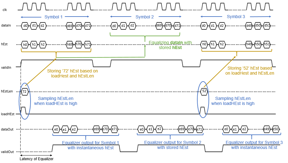
In this figure, you can see three symbols (Symbol 1, Symbol 2, and Symbol 3) are input to
the dataIn port. When the validIn input is
1 (high) and the loadHest input is
1 (high), the block samples the hEstlLen input
value, which is 72 in this example. Based on the
hEstlLen value, for Symbol 1, the block provides the equalized output
for the instantaneous hEst input values. When the
loadHest value changes to 0 (low), the block stores
the hEst values and provides the equalized output for Symbol 2 based on
the stored hEst values. The hEstLen value remains
the same until the loadHest changes to 0 (low).
Similarly, for Symbol 3, the block provides the equalized output for the instantaneous
hEst values based on the hEstlLen value, which is
52 in this example.
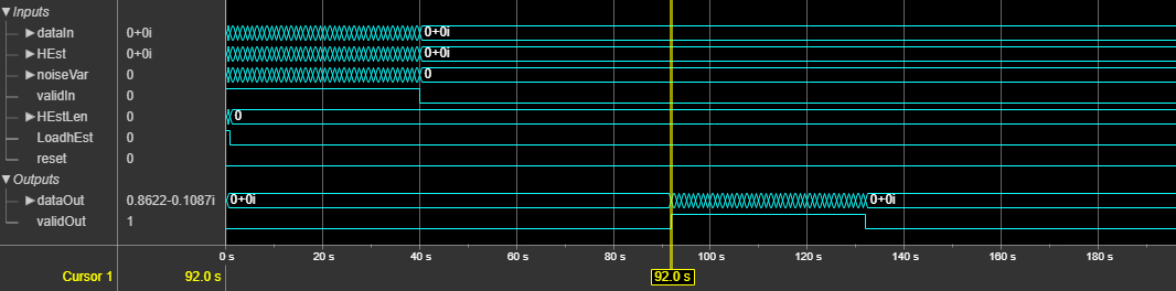
This figure shows a sample output of the OFDM Equalizer block when you
set the Equalization method parameter to MMSE and
the Maximum length of channel estimate per symbol parameter to
52. The latency of the block is 92 clock cycles.
References
[1] 3GPP TS 36.211 version 14.2.0 Release 14. "Physical channels and modulation." LTE - Evolved Universal Terrestrial Radio Access (E-UTRA).
[2] 3GPP TS 38.212. “NR; Multiplexing and Channel Coding.” 3rd Generation Partnership Project; Technical Specification Group Radio Access Network.
[3] "Wireless LAN Medium Access Control (MAC) and Physical layer (PHY) Specifications." IEEE Std 802.11 – 2012.
Extended Capabilities
Version History
Introduced in R2021a
See Also
Blocks
Functions
nrEqualizeMMSE(5G Toolbox) |lteEqualizeMMSE(LTE Toolbox) |lteEqualizeZF(LTE Toolbox)