Collaborative Coexistence of WLAN, Bluetooth LE, and BR/EDR Using PHY Packet Traffic Arbitration
This example shows how to simulate collaborative coexistence of WLAN, Bluetooth® low energy (LE), and Bluetooth basic rate/enhanced data rate (BR/EDR) networks with physical layer (PHY) packet traffic arbitration (PTA).
Using this example, you can:
Create and configure a coexistence node consisting of WLAN, Bluetooth LE, and Bluetooth BR/EDR devices.
Add and configure PTA in the coexistence node.
Add On-Off application traffic between the devices.
Simulate the collaborative coexistence scenario and analyze the performance of each node.
Visualize the packet communication in the time and frequency domains for all the nodes.
Additionally, you can use this example script to perform these tasks.
Packet Traffic Arbitration
In collaborative coexistence mechanisms, two wireless networks collaborate and exchange network-related information. According to the recommended practices stated in [3], the three collaborative coexistence mechanisms are alternating wireless medium access (AWMA), PTA, and deterministic interference suppression. For more information about coexistence between Bluetooth and WLAN, see Bluetooth-WLAN Coexistence. This example simulates collaborative coexistence between Bluetooth and WLAN by using the PTA mechanism.
The PTA mechanism provides per-packet authorization for all transmissions and receptions. Bluetooth and WLAN technologies collocated in a device can collaboratively coexist by using the PTA mechanism. This example controls the transmission of packets by implementing PTA at the PHY.
If a node wants to transmit multiple packets simultaneously, PTA selects the packets to be transmitted.
If a node has two incoming packets at the same time, PTA decides whether the packets are processed by the WLAN or Bluetooth device.
If an ongoing transmission or reception exists in a device or PTA-linked devices, the PTA mechanism considers all other packets destined for this device as interference and does not process them.
If an ongoing transmission or reception exists in a device or PTA-linked devices, PTA disables transmission from that device.
If PTA is not connected to a device, the device has its own transmit-receive chain.
If you connect PTA to two or more devices, all the devices share the same transmit-receive chain.
In this example, the PTA transmits packets in this priority.
Bluetooth LE packets when CIS is configured
BR/EDR packets when SCO is configured
WLAN packets
Bluetooth LE packets
Bluetooth BR/EDR packets
Collaborative Coexistence Scenario
This figure shows a coexistence node consisting of a WLAN device and a Bluetooth device.
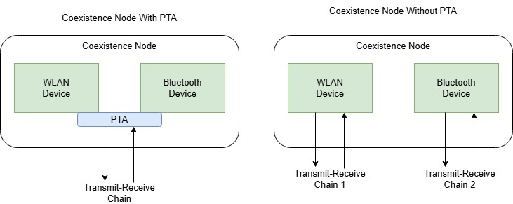
In the coexistence node, the PTA controls the communication to and from the WLAN and Bluetooth devices by using a single transmit-receive chain. In the absence of PTA, the WLAN and Bluetooth devices operate using their respective transmit-receive chains. The example creates and configures the coexistence node by performing these steps.
Create a coexistence node by using the
helperCoexNodehelper object.Add Bluetooth and WLAN devices to the coexistence node by using the
addDeviceobject function of thehelperCoexNodehelper object.Add a PTA module between the devices by using the
addPTAobject function of thehelperCoexNodeobject.Configure the connection for WLAN and Bluetooth devices.
Add application traffic between the devices.
The example simulates this coexistence scenario.
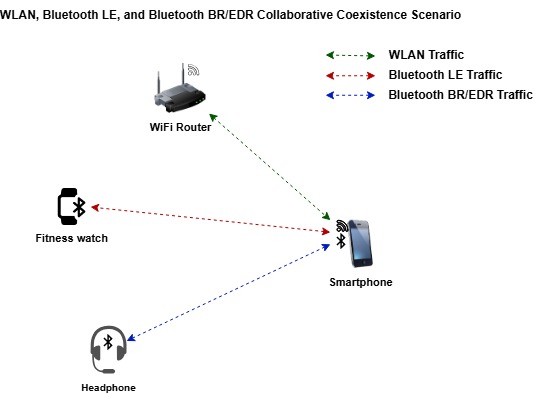
The scenario consists of these nodes.
Smartphone — This node is a multi-device coexistence node consisting of a WLAN device in a station (STA) role, a Bluetooth LE device in a Central role, and a Bluetooth BR/EDR device in a Central role. The smartphone includes a PTA module that coordinates the transmissions to avoid interference.
WiFi Router — This node is a coexistence node consisting of a WLAN access point (AP) device that is connected to the WLAN STA device in the smartphone.
Fitness watch — This node is a coexistence node consisting of a Bluetooth LE Peripheral device that is connected to the Bluetooth LE Central device in the smartphone.
Headphone — This node is a coexistence node consisting of a Bluetooth BR/EDR Peripheral device that is connected to the Bluetooth BR/EDR Central device in the smartphone.
Create and Configure the Scenario
Set the seed for the random number generator to 1 to ensure repeatability of results. The seed value controls the pattern of random number generation. Initializing the random number generator using the same seed ensures the same result. To improve the accuracy of your simulation results after running the simulation, you can change the seed value, run the simulation again, and average the results over multiple simulations.
rng(1,"twister")Create a wireless network simulator object.
networkSimulator = wirelessNetworkSimulator.init;
Specify the simulation time in seconds.
simulationTime = 0.5;
Create a multi-device coexistence node. Specify the name and the position of the node in meters.
coexistenceNode = helperCoexNode(Name="CoexNode",Position=[0 0 5]);Create a WLAN STA device by using the wlanDeviceConfig object. Use the configuration to add the WLAN STA device to the coexistence node.
staDeviceCfg = wlanDeviceConfig(Mode="STA",BandAndChannel=[2.4 1],InterferenceModeling="overlapping-adjacent-channel");
wlanSTADeviceName = addDevice(coexistenceNode,staDeviceCfg);
Create a Bluetooth LE device configuration. Use the configuration to add the Bluetooth LE Central device to the coexistence node.
centralLEDeviceCfg = helperBluetoothLEDeviceConfig(Role="central",TransmitterPower=0);
centralLEDeviceName = addDevice(coexistenceNode,centralLEDeviceCfg);
Create a Bluetooth BR/EDR device configuration. Use the configuration to add the Bluetooth BR/EDR Central device to the coexistence node.
centralBREDRDeviceCfg = helperBluetoothDeviceConfig(Role="central");
centralBRDeviceName = addDevice(coexistenceNode,centralBREDRDeviceCfg);
Create and configure a coexistence node with a WLAN AP device.
apDeviceCfg = wlanDeviceConfig(Mode="AP",BandAndChannel=[2.4 1],InterferenceModeling="overlapping-adjacent-channel");
wlanAPNode = helperCoexNode(Name="AP",Position=[20 0 0]);
wlanAPDeviceName = addDevice(wlanAPNode,apDeviceCfg);
Create and configure a coexistence node with a Bluetooth LE Peripheral device.
peripheralLENode = helperCoexNode(Name="Peripheral LE",Position=[0 0 0]);
peripheralLEDeviceName = addDevice(peripheralLENode,helperBluetoothLEDeviceConfig(TransmitterPower=0));
Create and configure a coexistence node with a Bluetooth BR/EDR Peripheral device.
peripheralBREDRNode = helperCoexNode(Name="Peripheral BREDR",Position=[10 0 0]);
peripheralBRDeviceName = addDevice(peripheralBREDRNode,helperBluetoothDeviceConfig);
Configure the Connections Between the Devices
Associate the WLAN AP and WLAN STA devices of the coexistence node.
associateStations(wlanAPNode,coexistenceNode);
Configure the connection between the Bluetooth LE Central and Peripheral devices of the coexistence node.
connectionCfgLE = helperBluetoothLEConnectionConfig;
configureConnection(connectionCfgLE,coexistenceNode,peripheralLENode);
Configure the connection between the Bluetooth BR/EDR Central and Peripheral devices of the coexistence node.
connectionCfgBREDR = helperBluetoothConnectionConfig(TransmitterPower=0);
configureConnection(connectionCfgBREDR,coexistenceNode,peripheralBREDRNode);
Visualize Wireless Network
To visualize the nodes in Bluetooth collaborative coexistence network, use the wirelessNetworkViewer object. The visualization shows the node placements in the Cartesian plane. To add the nodes to the wireless network viewer, use the addNodes object function of the wirelessNetworkViewer object.
netViewerObj = wirelessNetworkViewer();
addNodes(netViewerObj,coexistenceNode,Type="Coexistence node");
addNodes(netViewerObj,wlanAPNode,Type="WLAN AP");
addNodes(netViewerObj,peripheralLENode,Type="Peripheral LE node");
addNodes(netViewerObj,peripheralBREDRNode,Type="Peripheral BREDR node");

Add Application Traffic
This example consists of only one multidevice coexistence node. If you add traffic between a multidevice coexistence node and a single device coexistence node, the addTrafficSource object function automatically directs the traffic based on the type of the single device. To add traffic between two multidevice nodes, specify the SourceDeviceName name-value argument to the addTrafficSource object function. The value of the SourceDeviceName argument must be the name of the device that the addDevice object function returns.
Configure and add On-Off application traffic at the WLAN AP and STA nodes.
trafficWLAN = networkTrafficOnOff(DataRate=1000,PacketSize=1200,OnTime=0.1,OffTime=0.1);
addTrafficSource(wlanAPNode,trafficWLAN,DestinationNode=coexistenceNode);
addTrafficSource(coexistenceNode,trafficWLAN,DestinationNode=wlanAPNode);
Configure and add On-Off application traffic between the Bluetooth LE Central and the Peripheral nodes.
trafficLE = networkTrafficOnOff(DataRate=200,PacketSize=27,OnTime=Inf,OffTime=0);
addTrafficSource(coexistenceNode,trafficLE,DestinationNode=peripheralLENode);
addTrafficSource(peripheralLENode,trafficLE,DestinationNode=coexistenceNode);
Configure and add On-Off application traffic between the Bluetooth BR/EDR Central and Peripheral nodes.
trafficBREDR = networkTrafficOnOff(DataRate=200,PacketSize=27,OnTime=0.1,OffTime=0.1);
addTrafficSource(coexistenceNode,trafficBREDR,DestinationNode=peripheralBREDRNode);
addTrafficSource(peripheralBREDRNode,trafficBREDR,DestinationNode=coexistenceNode);
Attach PTA
To add a PTA to the multidevice coexistence node, set the enablePTA flag to true.
enablePTA =  true;
true;Add a PTA to the coexistence node by using the addPTA object function. The helperPHYPTAModule function works as follows.
The function checks all the packets present in the coexistence node buffer according to a pre-defined priority order and decides which packet type to grant.
If any PTA linked device is already transmitting or receiving, the PTA does not allow a new packet grant and returns 0.
The PTA module uses the following packet priority order, from highest to lowest.
LE CIS Packet
BR/EDR SCO Packet
WLAN Packet
Other LE packets
Other BR/EDR Packets
if enablePTA
    ptaHandle = @(coexObj,currentTime) helperPHYPTAModule(coexObj,currentTime);
    addPTA(coexistenceNode,ptaHandle);
end
Simulation and Results
Add all the nodes to the wireless network simulator.
addNodes(networkSimulator,[coexistenceNode wlanAPNode peripheralLENode peripheralBREDRNode]);
nodes = networkSimulator.Nodes;
Configure Packet Communication and Node Performance Visualization
To visualize packet communication in all the nodes, set the enablePacketVisualization flag to true. The visualization shows these plots.
Packet communication over the time and frequency domains.
State transitions of WLAN and Bluetooth packets for each node over time.
At the end of the simulation, you can visualize packets at any time instance.
enablePacketVisualization =  true;
true;Initialize the visualization by using the wirelessTrafficViewer object. Add the nodes to the traffic viewer by using the addNodes object function of wirelessTrafficViewer object. To configure the wireless traffic viewer for collaborative coexistence node support, use the helperCustomNodeTrafficViewer helper function.
if enablePacketVisualization
    viewerObj = wirelessTrafficViewer;
    addNodes(viewerObj,nodes);
    helperCustomNodeTrafficViewer(viewerObj,nodes);
end
To view the node performance visualization, set enableNodePerformancePlot to true. The visualization displays the packet loss ratio, throughput, and latency of the WLAN, Bluetooth LE, and Bluetooth BR/EDR nodes at the end of simulation.
enableNodePerformancePlot =  true;
true;Calculate the node performance by using the helperPerformanceViewer helper object.
performancePlotObj = helperPerformanceViewer(nodes,simulationTime);
Run the Simulation
Run the simulation for the time specified and generate these results.
A runtime plot for all the nodes, showing the state transitions and packet transmissions over the time and frequency domains.
A bar plot for all the nodes showing the packet loss ratio, throughput, and average application layer (APP) packet latency. You can find these results in the
performancePlotObjvariable.The APP, link layer (LL), and PHY statistics for all the nodes simulated.
run(networkSimulator,simulationTime);


The plotNetworkStats object function displays these simulation plots.
LL throughput (in Mbps) at each node.
LL packet loss ratio (ratio of unsuccessful data transmissions to the total data transmissions) at each node.
Average application packet latency (in seconds) incurred at each node.
if enableNodePerformancePlot
    plotNetworkStats(performancePlotObj);
end

Statistics
Retrieve the statistics of all the nodes. In the coexistence node, the WLAN, Bluetooth LE, and Bluetooth BR/EDR node statistics are present in their corresponding device structures For more information about WLAN node statistics, see WLAN System-Level Simulation Statistics. For more information about Bluetooth LE and BR/EDR node statistics, see Bluetooth LE Node Statistics (Bluetooth Toolbox) and Bluetooth BR/EDR Node Statistics (Bluetooth Toolbox), respectively.
coexNodeStats = statistics(coexistenceNode);
apStats = statistics(wlanAPNode);
peripheralLEStats = statistics(peripheralLENode);
peripheralBREDRStats = statistics(peripheralBREDRNode);
Further Exploration
You can use this example to further explore these capabilities.
Capture IQ Samples
Capture the IQ samples of the nodes by using the wirelessIQLogger object. To capture the IQ samples of the coexistence node, uncomment and add this code before you run the wireless network simulator.
% iqSampleObj = wirelessIQLogger(coexistenceNode,FileName=["CoexWLAN" "CoexBREDR" "CoexLE"]);At the end of the simulation, the simulation stores the IQ samples of the corresponding PHY in the nodes in a MAT file with the filename format NodeName_NodeID_CenterFrequency_Bandiwdth_yyyyMMdd_HHmmss.mat, where:
NodeName — Name of the node.
NodeID — Numeric ID of the node.
CenterFrequency — Operating center frequency of the PHY.
Bandwidth — Operating bandwidth of the PHY.
yyyyMMdd — Date of file creation, in the format year, month, day.
HHmmss — Time of file creation, in the format hour, minute, second, using the 24-hour clock format.
A MAT file corresponding to each node stores the captured IQ samples. If the network contains several nodes or when the simulation time is long, the process of capturing the IQ samples consume significant memory. The MAT file generated at the end of the simulation can consume significant disk space. For example, a system-level simulation that captures 1000 million IQ samples creates a MAT file of approximate size 8 GB.
To visualize the captured IQ samples, use the Signal Analyzer app. Uncomment and add the code after running the simulation to visualize the IQ samples of the LE device in the coexistence node.
% iqSamples = load("CoexLE.mat");
% signalAnalyzer(iqSamples.Waveform);
Add Mobility to Nodes
You can add mobility to any node by using the addMobility object function. To add mobility to the coexistence node, uncomment and add this code before you run the wireless network simulator.
% addMobility(coexistenceNode,BoundaryShape="rectangle",RefreshInterval=0.1)Add Antenna Isolation
Antenna isolation is the isolation between the antennas in the transmit-receive chains present in the same coexistence node. Isolation between two antennas minimizes the interference on each antenna caused by the adjacent antenna. To add antenna isolation between the transmit-receive chains in a coexistence node, use the configureAntennaIsolation object function of the helperCoexNode helper object. Uncomment and add this code before you run the wireless network simulator.
% isolationPower = 20; % In dB
% configureAntennaIsolation(coexistenceNode,isolationPower)
Appendix
The example uses these helpers:
helperCoexNode— Create a collaborative coexistence nodehelperBluetoothLEDeviceConfig— Create Bluetooth LE device configuration object for coexistence nodehelperBluetoothDeviceConfig— Create Bluetooth BR/EDR device configuration object for coexistence nodehelperBluetoothLEConnectionConfig— Create Bluetooth LE connection configuration object for coexistence nodehelperBluetoothConnectionConfig— Create Bluetooth BR/EDR connection configuration object for coexistence nodehelperPHYPTAModule— PHY PTA module to determine the packet that needs to be transmittedhelperScatternetBaseband— Create an object for modeling Bluetooth BR/EDR baseband layer for central, peripheral, and central-peripheral roleshelperPerformanceViewer— Return a performance metrics viewer objecthelperCustomNodeTrafficViewer— Visualize the packet communication between custom nodes in wireless traffic viewer
References
Bluetooth Technology Website. “Bluetooth Technology Website | The Official Website of Bluetooth Technology.” Accessed November 04, 2025. https://www.bluetooth.com/.
Bluetooth Special Interest Group (SIG). "Bluetooth Core Specification". Version 6.1 https://www.bluetooth.com/
Institute of Electrical and Electronics Engineers (IEEE). “IEEE Recommended Practice for Information Technology-- Local and Metropolitan Area Networks-- Specific Requirements-- Part 15.2: Coexistence of Wireless Personal Area Networks with Other Wireless Devices Operating in Unlicensed Frequency Bands.” IEEE Standard 802.15.2. IEEE, August 28, 2003. https://doi.org/10.1109/IEEESTD.2003.94386.
Institute of Electrical and Electronics Engineers (IEEE). "IEEE Standard for Information Technology--Telecommunications and Information Exchange between Systems Local and Metropolitan Area Networks--Specific Requirements Part 11: Wireless LAN Medium Access Control (MAC) and Physical Layer (PHY) Specifications Amendment 1: Enhancements for High-Efficiency WLAN." IEEE 802.11ax-2021. IEEE, May 19, 2021. https://doi.org/10.1109/IEEESTD.2021.9442429.
Institute of Electrical and Electronics Engineers (IEEE). TGax Simulation Scenarios. IEEE 802.11-14/0980r16. IEEE, 2015.
Institute of Electrical and Electronics Engineers (IEEE). 11ax Evaluation Methodology. IEEE 802.11-14/0571r12. IEEE, January 2016.
"IEEE Draft Recommended Practice for Information Technology Telecommunications and Information Exchange Between Systems Local and Metropolitan Area Networks Specific Requirements-Part 15.2: Coexistence of Wireless Personal Area Networks With Other Wireless Devices Operating in Unlicensed Frequency Bands (Replaced by IEEE 802.15.2-2003)." IEEE Std P802.15.2/D09, 2003. https://ieeexplore.ieee.org/document/4040972.
See Also
Objects
wirelessIQLogger(Wireless Network Toolbox) |wirelessTrafficViewer(Wireless Network Toolbox) |wirelessNetworkViewer(Wireless Network Toolbox) |wirelessNetworkEventTracer(Wireless Network Toolbox)