NR PUCCH Block Error Rate
This example shows how to measure the block error rate (BLER) of uplink control information (UCI) transmitted on the physical uplink control channel (PUCCH) in a 5G NR link using 5G Toolbox™ features.
Introduction
This example measures the BLER of UCI transmitted on PUCCH format 3 of a 5G link.
The UCI BLER is defined as the probability of incorrectly decoding the UCI when the UCI is transmitted:
is the number of instances when transmitted UCI is incorrectly decoded.
is the number of instances when UCI is transmitted.
These 5G NR features are modeled in this example.
UCI encoding and decoding
PUCCH and associated demodulation reference signal (DM-RS)
OFDM modulation and demodulation
Tapped delay line (TDL) propagation channel
Other features of the simulation in this example are:
Perfect or practical synchronization and channel estimation
Equalization
To reduce the total simulation time, you can use Parallel Computing Toolbox™ features to execute the signal to noise ratio (SNR) points of the SNR loop in parallel.
Simulation Length and SNR Points
Set the length of the simulation in terms of the number of 10 ms frames. A large number for NFrames must be used to produce meaningful throughput results. Set the SNR points to simulate. The SNR is defined per resource element (RE) and applies to each receive antenna. For an explanation of the SNR definition that this example uses, see SNR Definition Used in Link Simulations.
simParameters = struct;         % Create simParameters structure
simParameters.NFrames = 5;      % Number of 10 ms frames
simParameters.SNRIn = -14:2:-4; % SNR range (dB)
Set the displaySimulationInformation variable to true to display the information of BLER simulation at each SNR point.
displaySimulationInformation =  true;
true;Carrier and PUCCH Configuration
Set carrier with these properties:
Physical layer cell identity
Subcarrier spacing (SCS) in kHz
Cyclic prefix
Bandwidth in resource blocks (RBs). Each RB contains 12 subcarriers
Starting RB of the carrier with respect to the common resource block 0 (CRB 0)
Set PUCCH format 3 configuration with these properties:
Allocated set of RBs
Symbol allocation ([S L])
Modulation scheme
Frequency hopping configuration
Second hop starting RB
Group hopping configuration
Scrambling identities
Additional DM-RS configuration
Set these additional simulation-wide parameters:
Number of transmit antennas
Number of receive antennas
% Set carrier resource grid properties (15 kHz SCS and 10 MHz bandwidth) carrier = nrCarrierConfig; carrier.NCellID =0; carrier.SubcarrierSpacing =
15; carrier.CyclicPrefix =
"normal"; carrier.NSizeGrid = 52; carrier.NStartGrid = 0; % Set PUCCH format 3 properties pucch = nrPUCCH3Config; pucch.PRBSet = 0; pucch.SymbolAllocation = [0 14]; pucch.Modulation =
"QPSK"; pucch.FrequencyHopping =
"intraSlot"; pucch.SecondHopStartPRB = (carrier.NSizeGrid-1) - (numel(pucch.PRBSet)-1); pucch.GroupHopping =
"neither"; pucch.HoppingID = 0; pucch.NID = []; pucch.RNTI =
1; pucch.AdditionalDMRS =
0; % Set number of transmit and receive antennas simParameters.NTxAnts =
1; simParameters.NRxAnts =
2;
UCI Configuration
The field NumUCIBits indicates the number of random UCI bits used for generation of the UCI payload. The number of UCI bits must be in the range from 3 to 1706.
simParameters.NumUCIBits =16; % Number of UCI bits
Channel Estimator Configuration
The logical variable perfectChannelEstimator controls the channel estimation and synchronization behavior. When you set the value to true, the perfect channel estimation and synchronization is used. Otherwise, practical channel estimation and synchronization is used, based on the values of the received PUCCH DM-RS.
perfectChannelEstimator =  true;
true;Propagation Channel Model Configuration
Create the TDL channel model with the configuration of 'TDLC300-100 Low', specified in Annex G, Table G.2.1.1-4 of TS 38.104.
% Set up TDL channel
channel = nrTDLChannel;
channel.DelayProfile = 'TDLC300';
channel.MaximumDopplerShift = 100; % in Hz
channel.MIMOCorrelation = 'low';
channel.TransmissionDirection = 'Uplink';
channel.NumTransmitAntennas = simParameters.NTxAnts;
channel.NumReceiveAntennas = simParameters.NRxAnts;
Set the sampling rate for the channel model by using the value returned from the nrOFDMInfo function.
waveformInfo = nrOFDMInfo(carrier);
channel.SampleRate = waveformInfo.SampleRate;
Processing Loop and Results
To determine the BLER of UCI at each SNR point, the UCI transmitted on the PUCCH is analyzed per transmission instance using these steps.
Generate the resource grid: The
nrUCIEncodefunction encodes the UCI. ThenrPUCCHfunction modulates the encoded UCI. An implementation-specific multiple-input-multiple-output (MIMO) precoding is applied to the modulated symbols. These modulated symbols along with reference signal are mapped to the resource grid.Generate the waveform: The
nrOFDMModulatefunction OFDM-modulates the generated grid to get the time domain waveform.Model and apply a noisy channel: The generated waveform is passed through a TDL fading channel to get the faded waveform. Then, additive white Gaussian noise (AWGN) is added to the faded waveform. The SNR for each layer is defined per RE and per receive antenna. For an explanation of the SNR definition that this example uses, see SNR Definition Used in Link Simulations.
Perform synchronization and OFDM demodulation: For perfect synchronization, the path gains and path filters of the channel are used. For practical synchronization, the received waveform is correlated with the PUCCH DM-RS. The
nrOFDMDemodulatefunction then OFDM-demodulates the synchronized signal.Perform channel estimation: For perfect channel estimation, the path gains, path filters, and the sample times of channel snapshots are used. For practical channel estimation, the PUCCH DM-RS is used.
Extract the PUCCH and perform equalization: The
nrExtractResourcesfunction extracts the REs corresponding to the PUCCH allocation from the received OFDM resource grid and the estimated channel grid. ThenrEqualizeMMSEfunction then equalizes the received PUCCH REs.Decode the PUCCH: The equalized PUCCH symbols, along with a noise estimate, are demodulated and descrambled to obtain an estimate of the received codeword.
Decode the UCI: The decoded codeword is passed through the
nrUCIDecodefunction, and the number of instances of incorrect UCI decoding is recorded.
% Obtain channel information
chInfo = info(channel);

% Specify array to store output(s) for all SNR points
blerUCI = zeros(length(simParameters.SNRIn),1);

% Assign temporary variables for parallel simulation
nTxAnts = simParameters.NTxAnts;
nRxAnts = simParameters.NRxAnts;
snrIn = simParameters.SNRIn;
nFrames = simParameters.NFrames;
ouci = simParameters.NumUCIBits;
nFFT = waveformInfo.Nfft;
symbolsPerSlot = carrier.SymbolsPerSlot;
slotsPerFrame = carrier.SlotsPerFrame;

% Validate number of frames
validateattributes(nFrames,{'double'},{'scalar','positive','integer'},'','simParameters.NFrames')

% Validate SNR range
validateattributes(snrIn,{'double'},{'real','vector','finite'},'','simParameters.SNRIn')

% Validate PUCCH configuration
classPUCCH = validatestring(class(pucch),{'nrPUCCH2Config','nrPUCCH3Config','nrPUCCH4Config'},'','class of PUCCH');
formatPUCCH = classPUCCH(8);

% The temporary variables carrier_init and pucch_init are used to
% create the temporary variables carrier and pucch in the SNR loop
% to create independent instances in case of parallel simulation.
carrier_init = carrier;
pucch_init = pucch;

for snrIdx = 1:numel(snrIn) % Comment out for parallel computing
% parfor snrIdx = 1:numel(snrIn) % Uncomment for parallel computing
    % To reduce the total simulation time, you can execute this loop in
    % parallel by using Parallel Computing Toolbox features. Comment out the
    % for-loop statement and uncomment the parfor-loop statement. If
    % Parallel Computing Toolbox is not installed, parfor-loop defaults to
    % a for-loop statement. Because the parfor-loop iterations are executed
    % in parallel in a nondeterministic order, the simulation information
    % displayed for each SNR point can be intertwined. To switch off the
    % simulation information display, set the displaySimulationInformation
    % variable (defined earlier in this example) to false.

    % Reset the random number generator and channel so that each SNR point
    % experiences the same noise and channel realizations.
    rng(0,'twister')
    reset(channel)

    % Initialize variables for this SNR point (required when using
    % Parallel Computing Toolbox)
    carrier = carrier_init;
    pucch = pucch_init;
    pathFilters = [];

    % Get operating SNR value
    SNRdB = snrIn(snrIdx);

    % Get total number of slots in the simulation period
    NSlots = nFrames*slotsPerFrame;

    % Set timing offset, which is updated in every slot for perfect
    % synchronization and when correlation is strong for practical
    % synchronization
    offset = 0;

    % Set variable to store block errors for each SNR point with 0
    ucierr = 0;
    for nslot = 0:NSlots-1

        % Update carrier slot number to account for new slot transmission
        carrier.NSlot = nslot;

        % Get PUCCH resources
        [pucchIndices,pucchIndicesInfo] = nrPUCCHIndices(carrier,pucch);
        dmrsIndices = nrPUCCHDMRSIndices(carrier,pucch);
        dmrsSymbols = nrPUCCHDMRS(carrier,pucch);

        % Create random UCI bits
        uci = randi([0 1],ouci,1);

        % Perform UCI encoding
        codedUCI = nrUCIEncode(uci,pucchIndicesInfo.G);

        % Perform PUCCH modulation
        pucchSymbols = nrPUCCH(carrier,pucch,codedUCI);

        % Create resource grid associated with PUCCH transmission antennas
        pucchGrid = nrResourceGrid(carrier,nTxAnts);

        % Perform implementation-specific PUCCH MIMO precoding and mapping
        F = eye(1,nTxAnts);
        [~,pucchAntIndices] = nrExtractResources(pucchIndices,pucchGrid);
        pucchGrid(pucchAntIndices) = pucchSymbols*F;

        % Perform implementation-specific PUCCH DM-RS MIMO precoding and mapping
        [~,dmrsAntIndices] = nrExtractResources(dmrsIndices,pucchGrid);
        pucchGrid(dmrsAntIndices) = dmrsSymbols*F;

        % Perform OFDM modulation
        txWaveform = nrOFDMModulate(carrier,pucchGrid);

        % Pass data through the channel model. Append zeros at the end of
        % the transmitted waveform to flush the channel content. These
        % zeros take into account any delay introduced in the channel. This
        % delay is a combination of the multipath delay and implementation
        % delay. This value can change depending on the sampling rate,
        % delay profile, and delay spread.
        txWaveformChDelay = [txWaveform; zeros(chInfo.MaximumChannelDelay,size(txWaveform,2))];
        [rxWaveform,pathGains,sampleTimes] = channel(txWaveformChDelay);

        % Add AWGN to the received time domain waveform. Normalize the
        % noise power by the size of the inverse fast Fourier transform
        % (IFFT) used in OFDM modulation, because the OFDM modulator
        % applies this normalization to the transmitted waveform. Also,
        % normalize the noise power by the number of receive antennas,
        % because the default behavior of the channel model is to apply
        % this normalization to the received waveform.
        SNR = 10^(SNRdB/20);
        N0 = 1/(sqrt(2.0*nRxAnts*nFFT)*SNR);
        noise = N0*complex(randn(size(rxWaveform)),randn(size(rxWaveform)));
        rxWaveform = rxWaveform + noise;

        % Perform synchronization
        if perfectChannelEstimator == 1
            % For perfect synchronization, use the information provided by
            % the channel to find the strongest multipath component.
            pathFilters = getPathFilters(channel);
            [offset,mag] = nrPerfectTimingEstimate(pathGains,pathFilters);
        else
            % For practical synchronization, correlate the received
            % waveform with the PUCCH DM-RS to give timing offset estimate
            % t and correlation magnitude mag. The function hSkipWeakTimingOffset
            % is used to update the receiver timing offset. If the correlation
            % peak in mag is weak, the current timing estimate t is ignored
            % and the previous estimate offset is used.
            [t,mag] = nrTimingEstimate(carrier,rxWaveform,dmrsIndices,dmrsSymbols);
            offset = hSkipWeakTimingOffset(offset,t,mag);

            % Display a warning if the estimated timing offset exceeds the
            % maximum channel delay
            if offset > chInfo.MaximumChannelDelay
                warning(['Estimated timing offset (%d) is greater than the maximum channel delay (%d).' ...
                    ' This will result in a decoding failure. This may be caused by low SNR,' ...
                    ' or not enough DM-RS symbols to synchronize successfully.'],offset,chInfo.MaximumChannelDelay);
            end
        end
        rxWaveform = rxWaveform(1+offset:end,:);

        % Perform OFDM demodulation on the received data to recreate the
        % resource grid. Include zero padding in the event that practical
        % synchronization results in an incomplete slot being demodulated.
        rxGrid = nrOFDMDemodulate(carrier,rxWaveform);
        [K,L,R] = size(rxGrid);
        if (L < symbolsPerSlot)
            rxGrid = cat(2,rxGrid,zeros(K,symbolsPerSlot-L,R));
        end

        % Perform channel estimation
        if perfectChannelEstimator == 1
            % For perfect channel estimation, use the value of the path
            % gains provided by the channel.
            estChannelGrid = nrPerfectChannelEstimate(carrier,pathGains,pathFilters,offset,sampleTimes);

            % Get the perfect noise estimate (from the noise realization).
            noiseGrid = nrOFDMDemodulate(carrier,noise(1+offset:end,:));
            noiseEst = var(noiseGrid(:));

            % Apply MIMO deprecoding to estChannelGrid to give an
            % estimate per transmission layer.
            K = size(estChannelGrid,1);
            estChannelGrid = reshape(estChannelGrid,K*symbolsPerSlot*nRxAnts,nTxAnts);
            estChannelGrid = estChannelGrid*F.';
            estChannelGrid = reshape(estChannelGrid,K,symbolsPerSlot,nRxAnts,[]);
        else
            % For practical channel estimation, use PUCCH DM-RS.
            [estChannelGrid,noiseEst] = nrChannelEstimate(carrier,rxGrid,dmrsIndices,dmrsSymbols);
        end

        % Get PUCCH REs from received grid and estimated channel grid
        [pucchRx,pucchHest] = nrExtractResources(pucchIndices,rxGrid,estChannelGrid);

        % Perform equalization
        [pucchEq,csi] = nrEqualizeMMSE(pucchRx,pucchHest,noiseEst);

        % Decode PUCCH symbols
        [uciLLRs,rxSymbols] = nrPUCCHDecode(carrier,pucch,ouci,pucchEq,noiseEst);

        % Decode UCI
        decucibits = nrUCIDecode(uciLLRs{1},ouci);

        % Store values to calculate BLER
        ucierr = ucierr + (~isequal(decucibits,uci));

    end

    % Calculate UCI BLER for each SNR point
    blerUCI(snrIdx) = ucierr/NSlots;

    % Display results dynamically
    if displaySimulationInformation == 1
        fprintf(['UCI BLER of PUCCH format ' formatPUCCH ' for ' num2str(nFrames) ' frame(s) at SNR ' num2str(snrIn(snrIdx)) ' dB: ' num2str(blerUCI(snrIdx)) '\n'])
    end
end
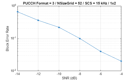
UCI BLER of PUCCH format 3 for 5 frame(s) at SNR -14 dB: 0.66
UCI BLER of PUCCH format 3 for 5 frame(s) at SNR -12 dB: 0.36
UCI BLER of PUCCH format 3 for 5 frame(s) at SNR -10 dB: 0.22
UCI BLER of PUCCH format 3 for 5 frame(s) at SNR -8 dB: 0.1
UCI BLER of PUCCH format 3 for 5 frame(s) at SNR -6 dB: 0.04
UCI BLER of PUCCH format 3 for 5 frame(s) at SNR -4 dB: 0.02
% Plot results
figure
semilogy(snrIn,blerUCI,'-*')
grid on
xlabel('SNR (dB)')
ylabel('Block Error Rate')
title(sprintf('PUCCH Format = %s / NSizeGrid = %d / SCS = %d kHz / %dx%d',...
    formatPUCCH,carrier_init.NSizeGrid,carrier_init.SubcarrierSpacing,nTxAnts,nRxAnts))
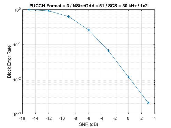
This next figure shows the BLER results obtained by simulating 1500 frames (NFrames = 1500, SNRIn = -15:3:3) for a carrier with 30 kHz SCS occupying a 20 MHz transmission bandwidth. The simulation setup includes the default PUCCH format 3 configuration placed in the example with the number of UCI bits set to 16 and the perfectChannelEstimator variable set to false.
Further Exploration
To analyze the UCI BLER at each SNR point, toggle the value of
perfectChannelEstimatorvariable and change the range of SNR values.To check the BLER performance of different scenarios, change the carrier numerology, the number of transmit and receive antennas, and the channel model.
To observe the BLER performance of PUCCH formats 2 and 4, use the
nrPUCCH2Configobject and thenrPUCCH4Configobject, respectively, for thepucchvariable in section Carrier and PUCCH Configuration.
Summary
The example demonstrates how to measure the UCI BLER when UCI is transmitted on PUCCH format 3. The example also displays and plots the BLER as a function of SNR.
References
3GPP TS 38.211. "NR; Physical channels and modulation (Release 15)." 3rd Generation Partnership Project; Technical Specification Group Radio Access Network.
3GPP TS 38.212. "NR; Multiplexing and channel coding (Release 15)." 3rd Generation Partnership Project; Technical Specification Group Radio Access Network.
3GPP TS 38.104. “NR; Base Station (BS) radio transmission and reception (Release 15).” 3rd Generation Partnership Project; Technical Specification Group Radio Access Network.