Model AUTOSAR Software Components
In Simulink®, you can flexibly model the structure and behavior of software components for the AUTOSAR Classic Platform. Components can contain one or multiple runnable entities, and can be single-instance or multi-instance. To design the internal behavior of components, you can use Simulink modeling styles, such as rate-based and function-call-based.
About AUTOSAR Software Components
An AUTOSAR application is made up of interconnected software components (SWCs). Each software component encapsulates a functional implementation of automotive behavior, with well-defined connection points to the outside world.
In Simulink, you can model:
Atomic software components — An atomic software component runs on exactly one automotive electronic control unit (ECU), and cannot be split into smaller software components.
Parameter software components — A parameter software component represents memory containing AUTOSAR calibration parameters, and provides parameter data to connected atomic software components.
The main focus of AUTOSAR modeling in Simulink is atomic software components. For information about parameter software components, see Model AUTOSAR Calibration Parameters and Lookup Tables.
Note
Do not confuse atomic in this context with the Simulink concept of atomic subsystems.
An AUTOSAR atomic software component interacts with other AUTOSAR software components or system services via well-defined connection points called ports which can be modeled using Inport and Outport blocks, or Simulink bus ports. One or more runnable entities (runnables) implement the behavior of the component.
Implementation Considerations
To develop an AUTOSAR atomic software component in Simulink, you create an initial Simulink representation of an AUTOSAR component, as described in Component Creation. You can either import an AUTOSAR component description from ARXML files or, in an existing model, build a default AUTOSAR component based on the model content. The resulting representation includes:
Simulink blocks, connections, and data that model AUTOSAR elements such as ports, runnables, inter-runnable variables (IRV), and parameters.
Stored properties, defined in the AUTOSAR standard, for AUTOSAR elements in the software component.
A mapping of Simulink elements to AUTOSAR elements.
Usually, the Simulink representation of an AUTOSAR component is a rate-based model, in which periodic runnables are modeled as atomic subsystems with periodic rates.
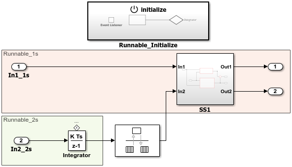
Consider the AUTOSAR example model autosar_swc. This model
shows a rate-based implementation of an AUTOSAR atomic software component. The model
implements periodic runnables using multiple rates. An Initialize Function
block initializes the component.
However, if your component design requires server functions or periodic function calls, you can use an export-function model. Models of this type contain Simulink Function blocks or function-call subsystems with periodic rates. For more information, see Export-Function Models Overview.
Consider the AUTOSAR example model autosar_swc_slfcns. This model shows a function-call-based
implementation of an AUTOSAR atomic software component. A the root-level, the model uses a
Simulink Function block and a periodic function-call subsystem. An
Initialize Function block initializes the component.
If your AUTOSAR software component design contains periodic runnables, you must decide whether your component requires a rate-based or function-call-based modeling approach. Before you create an initial Simulink representation of your AUTOSAR component, specify how to model periodic runnables:
If you are importing an AUTOSAR component description from ARXML files using
arxml.importerobject functioncreateComponentAsModel, set the propertyModelPeriodicRunnablesAstoAtomicSubsystem(default) for rate-based orFunctionCallSubsystemfor function-call based.If you are building a default AUTOSAR component in an existing model, populate the model with rate-based or function-call-based content.
For rate-based modeling, create model content with one or more periodic rates. To model an AUTOSAR inter-runnable variable, use a Rate Transition block that handles data transfers between blocks operating at different rates. The resulting component has
NNFor function-call based modeling create function-call subsystems at the top level of a model, or for client-server modeling, create Simulink Function blocks. Add root model inports and outports. To model an AUTOSAR inter-runnable variable, use a signal line to connect function-call subsystems. The resulting component has
NN
Select rate-based modeling, the default, unless your design requires function-call-based modeling.
Conditions in your AUTOSAR software component can prevent use of rate-based modeling if, for example, the AUTOSAR software component contains:
A server runnable
An inter-runnable variable (IRV) that multiple runnables read or write
A periodic runnable with a rate that is not a multiple of the fastest rate
Multiple runnables that access the same read or write data at different rates
A periodic runnable that other events also trigger
Multiple periodic runnables that are triggered at the same period
For examples of different ways to model AUTOSAR software components, see Rate-Based Components, Function-Call-Based Components, and Modeling Patterns for AUTOSAR Runnables.
Rate-Based Components
You can model AUTOSAR multirunnables using Simulink rate-based, multitasking modeling. First you create or import model content with multiple periodic rates. You can:
Create a software component with multiple periodic runnables in Simulink.
Import a software component with multiple periodic runnables from ARXML files into Simulink. Use
arxml.importerobject functioncreateComponentAsModelwith propertyModelPeriodicRunnablesAsset toAtomicSubsystem.Migrate an existing rate-based, multitasking Simulink model to the AUTOSAR target.
Root model inports and outports represent AUTOSAR ports, and Rate Transition blocks represent AUTOSAR inter-runnable variables (IRVs).
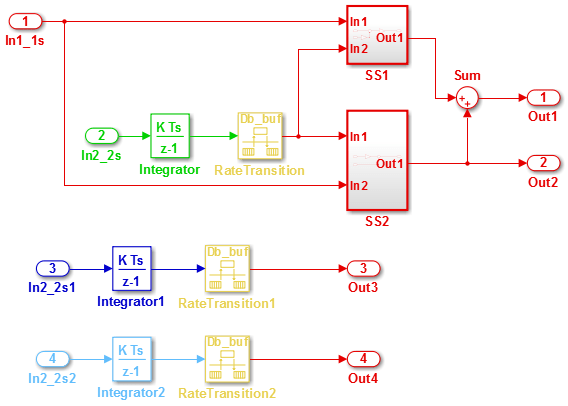
Here is an example of a rate-based, multitasking model that is suitable for simulation
and AUTOSAR code generation. (This example uses the example model mMultitasking_4rates.slx.) The model represents an AUTOSAR software
component. The colors displayed when you update the model (if colors are enabled on the
Debug tab, under Diagnostics > Information Overlays) represent the different periodic rates present. The Rate
Transition blocks represent AUTOSAR IRVs.
When you generate code, the model C code contains rate-grouped model step functions corresponding to AUTOSAR runnables, one for each discrete rate in the model. (The periodic step functions must be called in the manner of a rate-monotonic scheduler.) For more information, see Modeling Patterns for AUTOSAR Runnables.
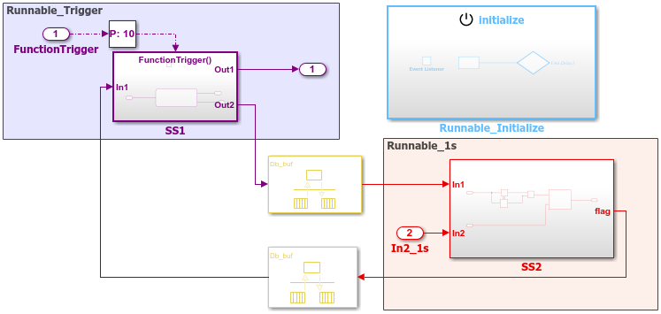
A rate-based AUTOSAR software component can include both periodic and asynchronous runnables. For example, in the JMAAB type beta architecture, an asynchronous trigger runnable interacts with periodic rate-based runnables.
Consider the AUTOSAR example model autosar_swc_fcncalls. This model shows a rate-based implementation of an
AUTOSAR atomic software component that includes an asynchronous (triggered) function-call
subsystem at root level. An Initialize Function block initializes the
component.
For more information, see Add Top-Level Asynchronous Trigger to Periodic Rate-Based System.
Function-Call-Based Components
You can model AUTOSAR multirunnables using Simulink function-call subsystems—or (for client-server modeling) Simulink Function blocks—at the top level of a model. First you create or import model content with multiple functions. You can:
Create a software component with multiple runnables modeled as function-call subsystems or Simulink Function blocks in Simulink.
Import a software component with multiple runnables from ARXML files into Simulink. Use
arxml.importerobject functioncreateComponentAsModelwith propertyModelPeriodicRunnablesAsset toFunctionCallSubsystem.Migrate an existing function-based Simulink model to the AUTOSAR target.
Root model inports and outports represent AUTOSAR ports, and signal lines connecting function-call subsystems represent AUTOSAR inter-runnable variables (IRVs).
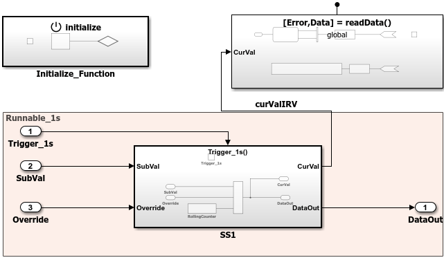
Here is an example of a function-call-based model, with multiple runnable entities, that
is suitable for simulation and AUTOSAR code generation. (This example uses AUTOSAR example
model autosar_swc_slfcns.) The model represents an AUTOSAR software
component. The function-call subsystem labeled SS1 and the
Simulink Function block readData represent runnables
that implement its behavior. An Initialize Function block initializes the
component. The signal line curValIRV represents an AUTOSAR IRV.
When you generate code, the model C code includes callable model entry-point functions corresponding to AUTOSAR runnables, one for each top-model function-call subsystem or Simulink Function block. For more information, see Modeling Patterns for AUTOSAR Runnables.
Multi-Instance Components
You can model multi-instance AUTOSAR software components in Simulink. For example, you can:
Map and configure a Simulink model as a multi-instance AUTOSAR software component, and validate the configuration. Use the
Reusable functionsetting of the model parameter Code interface packaging (Simulink Coder).Generate C code with reentrant runnable functions and multi-instance RTE API calls. You can access external I/O, calibration parameters, and per-instance memory, and use reusable subsystems in multi-instance mode.
Verify AUTOSAR multi-instance C code with software-in-the-loop (SIL) and processor-in-the-loop (PIL) simulations.
Import and export multi-instance AUTOSAR software component description XML files.
You can generate code for models configured as multi-instance AUTOSAR software components that contain global Simulink Function blocks. However, simulation of multi-instance AUTOSAR models that contain global Simulink Function blocks is not supported.
Note
Multi-instance AUTOSAR code generation is not supported for certain modeling patterns, including:
Models containing an S-function that is not code-reuse compliant
Subsystems triggered by multiple function calls
Models using queued sender-receiver communication with messages
Startup, Reset, and Shutdown
AUTOSAR applications sometimes require complex logic to execute during system initialization, reset, and termination sequences. To model startup, reset, and shutdown processing in an AUTOSAR software component, use the Simulink blocks Initialize Function and Terminate Function.
The Initialize Function and Terminate Function blocks can control execution of a component in response to initialize, reset, or terminate events. You can place the blocks at any level of a model hierarchy. Each nonvirtual subsystem can have its own set of initialize, reset, and terminate functions. In a lower level model, Simulink aggregates the content of the functions with corresponding instances in the parent model.
The Initialize Function and Terminate Function blocks
contain an Event Listener block. To specify the event
type of the function—Initialize,
Reset, or Terminate—use the
Event type parameter of the Event Listener block. In
addition, the function block reads or writes the state of conditions for other blocks. By
default, the Initialize Function block initializes the block state with the
State Writer block. Similarly, the
Terminate Function block saves the block state with the State
Reader block. When the function is triggered, the value of the state variable is
written to or read from the specified block.
AUTOSAR models can use the blocks to model potentially complex AUTOSAR startup, reset, and shutdown sequences. The subsystems work with any AUTOSAR component modeling style. (However, software-in-the-loop simulation of AUTOSAR initialize, reset, or terminate runnables works only with exported function modeling.)
In an AUTOSAR model, you map each Simulink initialize, reset, or terminate entry-point function to an AUTOSAR runnable.
For each runnable, configure the AUTOSAR event that activates the runnable. In general, you
can select any AUTOSAR event type except
TimingEvent.
For more information, see Configure AUTOSAR Initialize, Reset, or Terminate Runnables.
See Also
Rate Transition | Simulink Function | Initialize Function | Terminate Function | Event Listener | State Writer | State Reader
Topics
- Import AUTOSAR XML Descriptions Into Simulink
- Configure AUTOSAR Ports By Using Simulink Bus Ports
- Configure AUTOSAR Runnables and Events
- Configure AUTOSAR Initialize, Reset, or Terminate Runnables
- Add Top-Level Asynchronous Trigger to Periodic Rate-Based System
- Configure AUTOSAR Code Generation
- AUTOSAR Component Configuration
- Modeling Patterns for AUTOSAR Runnables