comm.GMSKModulator
Modulate using GMSK method
Description
The comm.GMSKModulator
System object™ modulates using the Gaussian minimum shift keying (GMSK) method. The output is a
baseband representation of the modulated signal. For more detail, see Algorithms.
To modulate a signal by using the GMSK method:
Create the
comm.GMSKModulatorobject and set its properties.Call the object with arguments, as if it were a function.
To learn more about how System objects work, see What Are System Objects?
Creation
Description
gmskmodulator = comm.GMSKModulator
gmskmodulator = comm.GMSKModulator(Name,Value)comm.GMSKModulator(PulseLength=6)
specifies the length of the Gaussian pulse shape as 6 symbol intervals.
Properties
Usage
Syntax
Description
Input Arguments
Output Arguments
Object Functions
To use an object function, specify the
System object as the first input argument. For
example, to release system resources of a System object named obj, use
this syntax:
release(obj)
Examples
Map binary sequences of zeros and ones to the output of a GMSK modulator. This mapping also applies for MSK modulation.
Create a GMSK modulator that accepts binary inputs and has pulse length and samples per symbol values of 1.
gmskmodulator = comm.GMSKModulator( ...
    BitInput=true, ...
    PulseLength=1, ...
    SamplesPerSymbol=1);
Create an input sequence of all zeros. Modulate the sequence.
x = zeros(5,1);
y = gmskmodulator(x)
y = 5×1 complex

   1.0000 + 0.0000i
   0.0000 - 1.0000i
  -1.0000 - 0.0000i
  -0.0000 + 1.0000i
   1.0000 + 0.0000i
Determine the phase angle for each point. Use the unwrap function to show the trend.
theta = unwrap(angle(y))
theta = 5×1

         0
   -1.5708
   -3.1416
   -4.7124
   -6.2832
A sequence of zeros causes the phase to shift by -π/2 between samples.
Reset the modulator. Modulate an input sequence of all ones.
reset(gmskmodulator)
x = ones(5,1);
y = gmskmodulator(x)
y = 5×1 complex

   1.0000 + 0.0000i
   0.0000 + 1.0000i
  -1.0000 + 0.0000i
  -0.0000 - 1.0000i
   1.0000 - 0.0000i
Determine the phase angle for each point. Use the unwrap function to show the trend.
theta = unwrap(angle(y))
theta = 5×1

         0
    1.5708
    3.1416
    4.7124
    6.2832
A sequence of ones causes the phase to shift by +π/2 between samples.
Create a GMSK modulator and demodulator pair. Create an AWGN channel object.
gmskmodulator = comm.GMSKModulator( ...
    BitInput=true, ...
    InitialPhaseOffset=pi/4);
gmskdemodulator = comm.GMSKDemodulator( ...
    BitOutput=true, ...
    InitialPhaseOffset=pi/4);
channel = comm.AWGNChannel( ...
    NoiseMethod='Signal to noise ratio (SNR)', ...
    SNR=0);
Create an error rate calculator and account for the delay between the modulator and demodulator, caused by the Viterbi algorithm.
errorRate = comm.ErrorRate( ...
    ReceiveDelay=gmskdemodulator.TracebackDepth);
Process 100 frames of data looping through these steps.
Generate vectors with 300 elements of random binary data.
GMSK-modulate the data.
Pass the modulated data through the AWGN channel.
GMSK-demodulate the data.
Collect error statistics on the frames of data.
for counter = 1:100
   % Transmit 100 3-bit words
   data = randi([0 1],300,1);
   modSignal = gmskmodulator(data);
   noisySignal = channel(modSignal);
   receivedData = gmskdemodulator(noisySignal);
   errorStats = errorRate(data, receivedData);
end
Display the error statistics.
fprintf('Error rate = %f\nNumber of errors = %d\n', ...
         errorStats(1), errorStats(2))
Error rate = 0.000133
Number of errors = 4
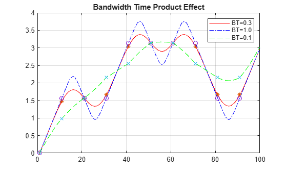
This example demonstrates the effect of bandwidth time (BT) product on a GMSK modulated signal.
Create a binary data vector and apply GMSK modulation to the data.
d = [0 1 1 0 1 0 0 1 1 1]';
a = comm.GMSKModulator(BitInput=true,SamplesPerSymbol=10)
a =
  comm.GMSKModulator with properties:

                BitInput: true
    BandwidthTimeProduct: 0.3000
             PulseLength: 4
        SymbolPrehistory: 1
      InitialPhaseOffset: 0
        SamplesPerSymbol: 10
          OutputDataType: 'double'
x = a(d);
BTa = sprintf('BT=%2.1f',a.BandwidthTimeProduct);
Plot the phase angles and use the unwrap function to show the trend better.
plot(unwrap(angle(x)),'red-');
title('Bandwidth Time Product Effect')
hold on;
plot(1:10:length(x),unwrap(angle(x(1:10:end))),'*');
grid on
Set the BT product to 1 and plot the phase angles in the same plot.
a = comm.GMSKModulator(BitInput=true, ...
    SamplesPerSymbol=10,BandwidthTimeProduct=1)
a =
comm.GMSKModulator with properties:
BitInput: true
BandwidthTimeProduct: 1
PulseLength: 4
SymbolPrehistory: 1
InitialPhaseOffset: 0
SamplesPerSymbol: 10
OutputDataType: 'double'
x = a(d);
BTb = sprintf('BT=%2.1f',a.BandwidthTimeProduct);
plot(unwrap(angle(x)),'blue-.');
plot(1:10:length(x),unwrap(angle(x(1:10:end))),'o');
Set the BT product to 0.1 and plot the phase angles in the same plot.
a = comm.GMSKModulator(BitInput=true, ...
    SamplesPerSymbol=10,BandwidthTimeProduct=0.1)
a =
comm.GMSKModulator with properties:
BitInput: true
BandwidthTimeProduct: 0.1000
PulseLength: 4
SymbolPrehistory: 1
InitialPhaseOffset: 0
SamplesPerSymbol: 10
OutputDataType: 'double'
BTc = sprintf('BT=%2.1f',a.BandwidthTimeProduct);The spread of this pulse is inversely proportional to the BT product and a lower BT causes a wider spread over the bit symbol period. The peak amplitude of the pulse is directly proportional to the BT product and a lower peak amplitude causes narrower spread over the bit symbol period. As the bandwidth of the pulse decreases, the pulse duration increases.
x = a(d);
plot(unwrap(angle(x)),'green--');
plot(1:10:length(x),unwrap(angle(x(1:10:end))),'x');
legend(BTa,'',BTb,'',BTc,'')
hold off;
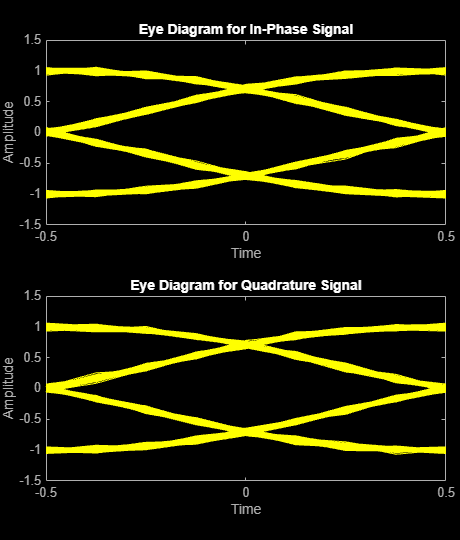
Compare Gaussian minimum shift keying (GMSK) and minimum shift keying (MSK) modulation schemes by plotting the eye diagram for GMSK with different pulse lengths and for MSK.
Set the samples per symbol variable.
sps = 8;
Generate random binary data.
data = randi([0 1],1000,1);
Create GMSK and MSK modulators that accept binary inputs. Set the PulseLength property of the GMSK modulator to 1.
gmskMod = comm.GMSKModulator( ...
    BitInput=true, ...
    PulseLength=1, ...
    SamplesPerSymbol=sps);
mskMod = comm.MSKModulator( ...
    BitInput=true, ...
    SamplesPerSymbol=sps);
Modulate the data using the GMSK and MSK modulators.
modSigGMSK = gmskMod(data);
modSigMSK = mskMod(data);
Pass the modulated signals through an AWGN channel having an SNR of 30 dB.
rxSigGMSK = awgn(modSigGMSK,30);
rxSigMSK = awgn(modSigMSK,30);
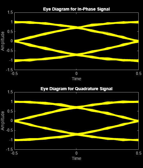
Use the eyediagram function to plot the eye diagrams of the noisy signals. With the GMSK pulse length set to 1, the eye diagrams are nearly identical.
eyediagram(rxSigGMSK,sps,1,sps/2)
eyediagram(rxSigMSK,sps,1,sps/2)
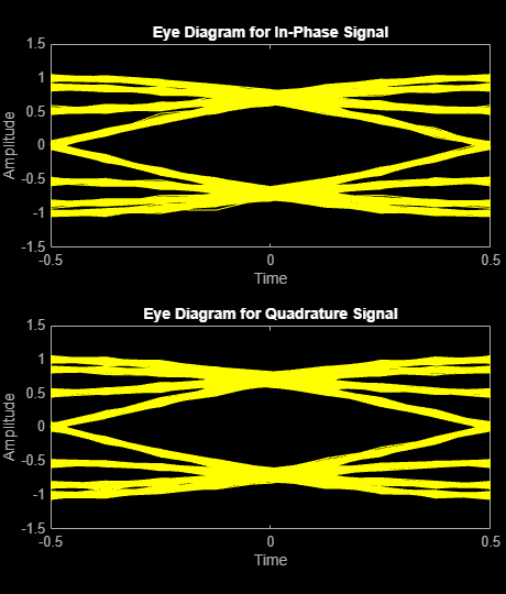
Set the PulseLength property for the GMSK modulator object to 3. Because the property is nontunable, the object must be released first.
release(gmskMod)
gmskMod.PulseLength = 3;
Generate a modulated signal using the updated GMSK modulator object and pass it through the AWGN channel.
modSigGMSK = gmskMod(data);
rxSigGMSK = awgn(modSigGMSK,30);
With continuous phase modulation (CPM) waveforms, such as GMSK, the waveform depends on values of the previous symbols as well as the present symbol. Plot the eye diagram of the GMSK signal to see that the increased pulse length results in an increase in the number of paths in the eye diagram.
eyediagram(rxSigGMSK,sps,1,sps/2)
Experiment by changing the PulseLength property of the GMSK modulator object to other values. If you set the property to an even number, you should set gmskMod.InitialPhaseOffset to pi/4 and update the offset argument of the eyediagram function from sps/2 to 0 for a better view of the modulated signal. In order to more clearly view the Gaussian pulse shape, you must use scopes that display the phase of the signal, as described in the View CPM Phase Tree Using Simulink example.
Algorithms
References
[1] Anderson, John B., Tor Aulin, and Carl-Erik Sundberg. Digital Phase Modulation. New York: Plenum Press, 1986.