Contenu principal

CPM Modulator Baseband

Modulate signal using CPM method

  • CPM Modulator Baseband block

Libraries:
Communications Toolbox / Modulation / Digital Baseband Modulation / CPM

Description

The CPM Modulator Baseband block modulates an input signal using the continuous phase modulation (CPM) method. The output of the modulator is a baseband representation of the modulated signal. For more information about the modulation and the filtering applied, see Algorithms.

Examples

expand all

The doc_cpm_phase_tree model uses the Eye Diagram block to view the in-phase and quadrature components, phase trajectory, phase tree, and instantaneous frequency of a CPM modulated signal.

Explore Model

A random integer signal is converted to bits and then CPM modulated. The CPM modulated signal values are converted from complex to magnitude, and angle, and then the phase is unwrapped.
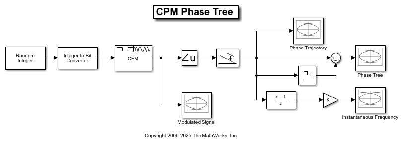
Plot Eye Diagrams

Eye Diagram blocks are named to reflect the signal each displays. When you run the example, these Eye Diagram blocks show how the CPM signal changes over time:

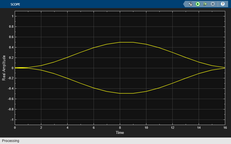
  • Modulated Signal block — Displays the in-phase and quadrature signals. Double-click the block to open the scope. The modulated signal is easy to see in the eye diagram only when the Modulation index parameter in the CPM Modulator Baseband block is set to 1/2. For a modulation index value of 2/3, the modulation is more complex and the features of the modulated signal are difficult to decipher. Unwrapping the phase and plotting it is another way to illustrate these more complex CPM modulated signals.

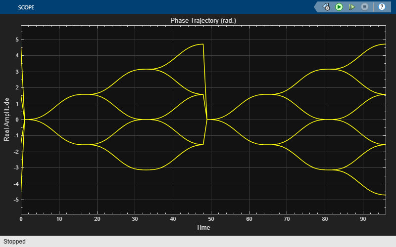
  • Phase Trajectory block — Displays the CPM phase. Double-click the block to open the scope. The Phase Trajectory block reveals that the signal phase is also difficult to view because it drifts with the data input to the modulator.

  • Phase Tree block — Displays the phase tree of the signal. The CPM phase is processed by a few simple blocks to make the CPM pulse shaping easier to view. This processing holds the phase at the beginning of the symbol interval and subtracts it from the signal. This zero-order hold resets the phase to zero every three symbols. The resulting plot shows the many phase trajectories that can be taken by the signal from any given symbol epoch.

  • Instantaneous Frequency block — Displays the instantaneous frequency of the signal. The CPM phase is differentiated to produce the frequency deviation of the signal. Viewing the CPM frequency signal enables you to observe the frequency deviation qualitatively, as well as make quantitative observations, such as measuring peak frequency deviation.

Running the doc_cpm_phase_tree model opens and plots the phase tree and instantaneous frequency eye diagram plots.

Further Exploration

To learn more about the example, try changing the following parameters in the CPM Modulator Baseband block:

  • Change Pulse length to a value between 1 and 6.

  • Change Frequency pulse shape to one of the other settings, such as Rectangular or Gaussian.

You can observe the effect of changing these parameters on the phase tree and instantaneous frequency of the modulated signal.

Ports

Input

expand all

Input signal, specified as a scalar or column vector. For more information, see Integer-Valued and Binary-Valued Input Signals.

This port is unnamed on the block.

Data Types: double | Boolean | int8 | int16 | int32

Output

expand all

CPM-modulated baseband signal, returned as a scalar or column vector. The modulated output symbols are oversampled by the Samples per symbol parameter value. For information on the processing rates, see Single-Rate Processing and Multirate Processing.

Use the Output data type parameter to specify the output data type.

This port is unnamed on the block.

Data Types: double | single

Parameters

expand all

To edit block parameters interactively, use the Property Inspector. From the Simulink® Toolstrip, on the Simulation tab, in the Prepare gallery, select Property Inspector.

Modulation order, specified as a power-of-two scalar. The modulation order M = 2k specifies the number of points in the symbol alphabet. k is a positive integer indicating the number of bits per symbol.

Integer or group of bits input indicator, specified as Integer or Bit.

  • Set this parameter to Integer to input data as integers.

  • Set this parameter to Bit to input data as bits.

For more information, see Integer-Valued and Binary-Valued Input Signals.

Symbol mapping of bit inputs, specified as Binary or Gray.

  • Set this parameter to Binary to map symbols using binary-coded ordering.

  • Set this parameter to Gray to map symbols using Gray-coded ordering.

For more information, see Integer-Valued and Binary-Valued Input Signals.

Dependencies

To enable this parameter, set Input type to Bit.

Modulation index {hi}, specified as a nonnegative scalar or column vector. The modulator operates in multi-h. For more information, see CPM Method.

Type of pulse shaping used to smooth the phase transitions of the modulated signal, specified as Rectangular, Raised Cosine, Spectral Raised Cosine, Gaussian, or Tamed FM. For more information, see Pulse Shape Filtering.

Main lobe duration of the largest lobe in the spectral raised cosine pulse, specified as a positive integer representing the number of symbol intervals used to pulse-shape the modulated signal.

Dependencies

To enable this parameter, set Frequency pulse shape to Spectral Raised Cosine.

Rolloff factor of the spectral raised cosine pulse, specified as a scalar in the range [0, 1].

Dependencies

To enable this parameter, set Frequency pulse shape to Spectral Raised Cosine.

Product of the bandwidth and symbol time of the Gaussian pulse shape, specified as a positive scalar. Use BT product to reduce the bandwidth, at the expense of increased intersymbol interference.

Dependencies

To enable this parameter, set Frequency pulse shape to Gaussian.

Length of the frequency pulse shape in symbol intervals, specified as a positive integer. For more information on the frequency pulse length, refer to LT in Pulse Shape Filtering.

Symbol prehistory, specified as a scalar or vector with odd integer elements. Values must be in the range [–(M – 1), (M – 1)]. M is the modulation order specified byM-ary number. The Symbol prehistory parameter defines the data symbols used by the modulator before the first call of the block, in reverse chronological order.

  • A scalar value expands to a vector of length LP – 1. LP represents the pulse length, which is specified by the Pulse length (symbol intervals) parameter.

  • For a vector, the length must be LP – 1.

Initial phase offset in radians, specified as a scalar. This property value is the initial phase offset of the modulated waveform.

Symbol sampling rate, specified as a positive integer. This parameter specifies the output symbol upsampling factor for each input sample.

For more information, see Signal Upsampling and Rate Changes.

Tip

To accurately model nonbinary pulse shapes, specifically pulse shapes other than rectangular, you should set the symbol sampling rate to values greater than 4.

Block processing rate, specified as one of these options:

  • Enforce single-rate processing — The input and output signals have the same sample time. The block implements the rate change by making a size change at the output when compared to the input. The output width equals the product of the number of symbols and the Samples per symbol parameter value.

  • Allow multirate processing — The input and output signals have different sample times. The output sample time equals the symbol period divided by the Samples per symbol parameter value.

Data type of the output, specified as double or single.

Block Characteristics

Data Types

Boolean | double | integer | single

Multidimensional Signals

no

Variable-Size Signals

no

More About

expand all

Algorithms

expand all

References

[1] Anderson, John B., Tor Aulin, and Carl-Erik Sundberg. Digital Phase Modulation. New York: Plenum Press, 1986.

[2] Proakis, John G. Digital Communications. 5th ed. New York: McGraw Hill, 2007.

Extended Capabilities

expand all

C/C++ Code Generation
Generate C and C++ code using Simulink® Coder™.

Version History

Introduced before R2006a