OSTBC Combiner
Combine inputs using orthogonal space-time block code
Libraries:
Communications Toolbox /
MIMO
Description
The OSTBC Combiner block combines the input signal (from all of the receive antennas) and the channel estimate signal to extract the soft information of the symbols encoded by an orthogonal space-time block code (OSTBC). The input channel estimate does not need to be constant and can vary each time you run the block. The combining algorithm uses only the estimate for the first symbol period per codeword block. A multiple-input multiple-output (MIMO) communications system applies symbol demodulation or decoding after the OSTBC combining process.
The block conducts the combining operation for each symbol independently. The combining algorithm depends on the structure of the OSTBC. For more information, see OSTBC Combining Algorithm.
Examples
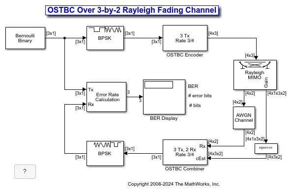
Simulate orthogonal space-time block codes (OSTBC) to achieve diversity gains in a multiple-input multiple-output (MIMO) communications system. The example shows the transmission of data over three transmit antennas and two receive antennas using independent Rayleigh fading per link.
Explore Model
The doc_ostc32 model creates a random binary signal, modulates it using a binary phase shift keying (BPSK) technique, and then encodes the waveform using a rate 3/4 orthogonal space-time block code for transmission over the fading channel. The fading channel has six independent links that result from the configuration of single-path Rayleigh fading processes. The simulation adds white Gaussian noise at the receiver, and then combines the signals from both receive antennas into a single stream for demodulation. For this combining process, the model assumes perfect knowledge of the channel gains at the receiver. The simulation compares the demodulated data with the original transmitted data and computes the bit error rate. The simulation runs until it processes 100 errors or 1e6 bits, whichever comes first.
Orthogonal Space-Time Block Code
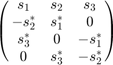
This matrix shows the rate 3/4 code with three transmit antenna orthogonal space-time block code configured in the OSTBC Encoder block:
where  ,
,  , and
, and  correspond to the three symbol inputs for which the output is given by the matrix. The input to the OSTBC Encoder block is a 3-by-1 vector signal and the output is a 4-by-3 matrix. The number of columns in the output signal indicates the number of transmit antennas for this simulation, where the first dimension is for time. The OSTBC Combiner block outputs a 3-by-1 vector.
For the rate 3/4 OSTBC code modeled, the output signal power per time step is 3x(3/4) = 2.25W. A channel symbol carries 3 data bits, is 4 time steps long, and has a period of 3e-3 seconds. At the receiver, two antennas result in 3/2 bits per symbol per channel (antenna). In addition,
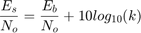
where k is the number of bits per symbol. Since the AWGN Channel block requires per-channel values for input signal power and number of bits per symbol, set the Es/No value to EbNo+10*log10(3/2) to calibrate the white Gaussian noise added in the simulation.
Performance
Compare the performance of the model to theoretical results by using the Bit Error Rate Analysis app. This plot compares the simulated BER for a range of Eb/No values with the theoretical results for a diversity order of six.
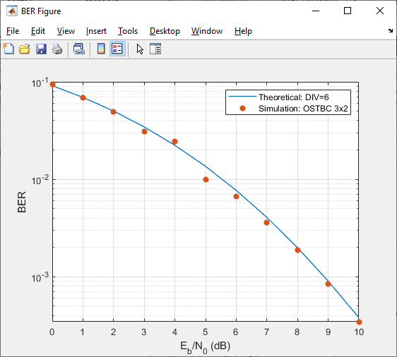
The theoretical and simulated results align well. The variation between theoretical and simulated results is primarily due to the simulated fading channel model having a small Doppler fade. Since the simulated channel varies slightly over the block symbols, the simulated and theoretical results show some variation.
Ports
Input
Output
Parameters
To edit block parameters interactively, use the Property Inspector. From the Simulink® Toolstrip, on the Simulation tab, in the Prepare gallery, select Property Inspector.
Main
Number of transmit antennas, specified as 2,
3, or 4.
Symbol rate of the code, specified as 3/4 or
1/2. When you set Number of
transmit antennas to 2, the symbol rate
is 1.
Dependencies
To enable this parameter, set Number of transmit
antennas to 3 or
4.
Number of receive antennas, specified as an integer in the range [1,8].
Data Types
Rounding mode for fixed-point calculations, specified as
Floor, Ceiling,
Convergent,
Nearest, Round,
Simplest, or Zero.
The block uses rounding method specified by this parameter to round off the
calculation to a representable number if a value cannot be represented
exactly by the specified data type and scaling. For more information, see
Rounding (Fixed-Point Designer).
For fixed-point calculations, use this parameter to specify the method to be used if the magnitude of a fixed-point calculation result does not fit into the range of the data type and scaling that stores the result.
To saturate on integer overflow, select this parameter.
To wrap on integer overflow, do not select this parameter.
For more information, see Precision and Range.
Data Types: Boolean
Complex product in the numerator for diversity combining, specified as
Inherit: Inherit via internal rule,
Inherit: Same as product output,
fixdt(1,16,0), or a custom
<data type expression>. For more
information, see Fixed-Point Signals.
Summation in the numerator for diversity combining. Fixed-point blocks that must hold summation results for further calculation usually allow you to specify the data type and scaling of the accumulator. Most such blocks cast to the accumulator data type before summation:

Use the Accumulator >> Mode parameter to specify how you would like to designate the accumulator word and fraction lengths:
When you select
Inherit via internal
                                        rule
, the accumulator output word and fraction lengths are automatically calculated for you. For more information, see Inherit via Internal Rule.When you select
Same as product
                                        output
, these characteristics match those of the product output.When you select
Same as input, these characteristics match those of the first input to the block.When you select
Binary point
                                        scaling
, you are able to enter the word length and the fraction length of the accumulator, in bits.When you select
Slope and bias
                                        scaling
, you are able to enter the word length, in bits, and the slope of the accumulator. The bias of all signals in DSP System Toolbox™ software is zero.
Complex product in the denominator for calculating total energy in the
MIMO channel, specified as Inherit: Inherit via internal
rule, Inherit: Same as product
output, fixdt(1,16,0), or a
custom <data type expression>.
Summation in the denominator for calculating total energy in the MIMO
channel, specified as Inherit: Inherit via internal
rule, Inherit: Same as
accumulator, Inherit: Same as energy product
output, fixdt(1,16,0), or a
custom <data type expression>
Normalized diversity combining by total energy in the MIMO channel,
specified as Inherit: Same as accumulator,
fixdt(1,16,0), or a custom
<data type expression>.
Block Characteristics
More About
To highlight the data types used for fixed-point signals, use this equation for for Alamouti code with one receive antenna:
In this equation, the data types for the Product output and Accumulator parameters correspond to the product and summation in the numerator. Similarly, the types for the Energy product output and Energy accumulator parameters correspond to the product and summation in the denominator.
Signal Flow Diagram for s1 Combining Calculation of Alamouti Code with One Receive Antenna

This equation shows the data types that the OSTBC combiner uses for fixed-point signals in the Alamouti code when the number of receive antennas, M, is greater than one.
Signal Flow Diagram for Complex Multiply of a + ib and c + id

For binary point scaling, you cannot specify WLp and FLp. Instead, the block determines these values implicitly from WLa and FLa.
The internal rule for the Product output and Energy product output parameters are:
When you select
Inherit via internal rule, the internal rule determines WLp and FLp. Therefore, WLa = WLp + 1 and FLa = FLpFor
Binary point scaling, you specify WLa and FLa. Therefore, WLp = WLa – 1 and FLa = FLp.
For information on how the internal rule applies to the Accumulator and Energy Accumulator parameters, see Inherit via Internal Rule.
Algorithms
Extended Capabilities
Version History
Introduced in R2009a