Digital Filter (Obsolete)
Filter each channel of input over time using static or time-varying digital filter implementations
Library
Filtering / Filter Implementations
dsparch4
Description
Note
Use of Digital Filter block in future releases is not recommended. Existing instances will continue to operate, but certain functionality will be disabled. We strongly recommend using one of Discrete FIR Filter (Simulink), Discrete Filter (Simulink), Biquad Filter, or Allpole Filter in new designs.
You can use the Digital Filter block to efficiently implement a floating-point or
fixed-point filter for which you know the coefficients, or that is already defined in a
dfilt object. The block independently filters each channel of
the input signal with a specified digital IIR or FIR filter. The block can implement
static filters with fixed coefficients, as well as
time-varying filters with coefficients that change over time.
You can tune the coefficients of a static filter during simulation.
This block filters each channel of the input signal independently over time. You must set the Input processing parameter to specify how the block interprets the input signal. You can select one of the following options:
Columns as channels (frame based)— When you select this option, the block treats each column of the input as an independent channel.Elements as channels (sample based)— When you select this option, the block treats each element of the input as an individual channel.
The output dimensions always match those of the input signal. The outputs of this
block numerically match the outputs of the Digital Filter Design block and of the dfilt
object.
Note
The Digital Filter block has direct feedthrough, so if you connect the output of this block back to its input you get an algebraic loop. For more information on direct feedthrough and algebraic loops, see Algebraic Loop Concepts (Simulink).
Sections of This Reference Page
Coefficient Source
The Digital Filter block can operate in three different modes. Select the mode in the Coefficient source group box.
Dialog parameters Enter information about the filter such as structure and coefficients in the block mask.
Input port(s) Enter the filter structure in the block mask, and the filter coefficients come in through one or more block ports. This mode is useful for specifying time-varying filters.
Discrete-time filter object (DFILT) Specify the filter using a
dfiltobject.
Supported Filter Structures
When you select Discrete-time filter object (DFILT), the
following dfilt structures are supported:
dfilt.df1dfilt.df1tdfilt.df2dfilt.df2tdfilt.df1sosdfilt.df1tsosdfilt.df2sosdfilt.df2tsosdfilt.dffirdfilt.dffirtdfilt.dfsymfirdfilt.dfasymfirdfilt.latticeardfilt.latticemamin
When you select Dialog parameters or Input
port(s), the list of filter structures offered in the
Filter structure parameter depends on whether you set the
Transfer function type to IIR (poles &
zeros), IIR (all poles), or
FIR (all zeros), as summarized in the following
table.
Note
Each structure listed in the table below supports both fixed-point and floating-point signals.
The table also shows the vector or matrix of filter coefficients you must provide for each filter structure.
Filter Structures and Filter Coefficients
Transfer Function Type | Supported Filter Structures | Filter Coefficient Specification |
|---|---|---|
IIR (poles & zeros) |
|
See Special Consideration for the Leading Denominator Coefficient. |
|
| |
IIR (all poles) |
| Denominator coefficients vector [a0, a1, a2, ..., am] See Special Consideration for the Leading Denominator Coefficient. |
| Reflection coefficients vector [k1, k2, ..., kn] | |
FIR (all zeros) |
| Numerator coefficients vector [b0, b1, b2, ..., bn] |
| Reflection coefficients vector [k1, k2, ..., kn] |
In some cases, the Digital Filter block requires the leading denominator
coefficient (a0) to be 1. This
requirement applies under the following conditions:
The Digital Filter block is operating in a fixed-point mode. The block operates in a fixed-point mode when at least one of the following statements is true:
The input to the Digital Filter block has a fixed-point or integer data type.
The Fixed-point instrumentation mode parameter under Analysis > Fixed Point Tool has a setting of
Minimums, maximums and overflows.
The Coefficient source has a setting of
DialogorInput port(s).Note
If you are working in one of the fixed-point situations described in the previous bullet, and the Coefficient source is set to
Input port(s), you must select the First denominator coefficient = 1, remove a0 term in the structure check box.The Transfer function type and Filter structure parameters are set to one of the combinations described in the following table.
Transfer function type Filter structure IIR (poles & zeros) Direct form IDirect form I transposedDirect form IIDirect form II transposedIIR (all poles) Direct formDirect form transposed
The Digital Filter block produces an error if you use it in one of these
configurations and your leading denominator coefficient
(a0) does not equal 1. To
resolve the error, set your leading denominator coefficient to 1 by scaling all
numerator and denominator coefficients by a factor of
a0.
Specifying Initial Conditions
In Dialog parameters and Input port(s) modes, the block initializes the internal filter states to zero by default, which is equivalent to assuming past inputs and outputs are zero. You can optionally use the Initial conditions parameter to specify nonzero initial conditions for the filter delays.
To determine the number of initial condition values you must specify, and how to specify them, see the following table on Valid Initial Conditions and Number of Delay Elements (Filter States). The Initial conditions parameter can take one of four forms as described in the following table.
Valid Initial Conditions
| Initial Condition | Examples | Description |
|---|---|---|
Scalar |
Each delay element for
each channel is set to | The block initializes all delay elements in the filter to the scalar value. |
Vector | For a filter with two delay elements: [d1 d2] The delay elements for all channels are d1 and d2. | Each vector element specifies a unique initial condition for a corresponding delay element. The block applies the same vector of initial conditions to each channel of the input signal. The vector length must equal the number of delay elements in the filter (specified in the table Number of Delay Elements (Filter States)). |
Vector or matrix | For a 3-channel input signal and a filter with two delay elements: [d1 d2 D1 D2 d1 d2] or
| Each vector or matrix element specifies a unique initial condition for a corresponding delay element in a corresponding channel:
|
Empty matrix |
| The empty matrix, |
The number of delay elements (filter states) per input channel depends on the filter structure, as indicated in the following table.
Number of Delay Elements (Filter States)
| Filter Structure | Number of Delay Elements per Channel |
|---|---|
|
|
|
|
|
|
|
|
|
|
State Logging
Simulink® enables you to log the states in your model to the MATLAB® workspace. The following table indicates which filter structures of the Digital Filter block support the Simulink state logging feature. See State (Simulink) for more information.
| Transfer Function Type | Filter Structure | State Logging Supported |
|---|---|---|
| IIR (poles & zeros) | Direct form I | No |
Direct form I transposed | Yes | |
Direct form II | No | |
Direct form II transposed | Yes | |
Biquadratic direct form I
(SOS) | Yes | |
Biquadratic direct form I transposed
(SOS) | Yes | |
Biquadratic direct form II
(SOS) | Yes | |
Biquadratic direct form II transposed
(SOS) | Yes | |
| IIR (all poles) | Direct form | No |
Direct form transposed | Yes | |
Lattice AR | Yes | |
| FIR (all zeros) | Direct form | No |
Direct form symmetric | No | |
Direct form antisymmetric | No | |
Direct form transposed | Yes | |
Lattice MA | Yes |
Fixed-Point Data Types
All structures supported by the Digital Filter block support fixed-point data types. You can specify intermediate fixed-point data types for quantities such as the coefficients, accumulator, and product output for each filter structure. See Filter Structure Diagrams for diagrams depicting the use of these intermediate fixed-point data types in each filter structure.
Dialog Box
Coefficient Source
The Digital Filter block can operate in three different modes. Select the mode in the Coefficient source group box.
Dialog parameters Enter information about the filter such as structure and coefficients in the block mask.
Input port(s) Enter the filter structure in the block mask, and the filter coefficients come in through one or more block ports. This mode is useful for specifying time-varying filters.
Discrete-time filter object (DFILT) Specify the filter using a
dfiltobject.
Different items appear on the Digital Filter block dialog depending on whether you select Dialog parameters, Input port(s), or Discrete-time filter object (DFILT) in the Coefficient source group box. See the following sections for details:
Specify Filter Characteristics in Dialog and/or Through Input Ports
The Main pane of the Digital Filter block dialog appears as follows when Dialog parameters is specified in the Coefficient source group box. The parameters below can appear when Dialog parameters or Input port(s) is selected, as noted.
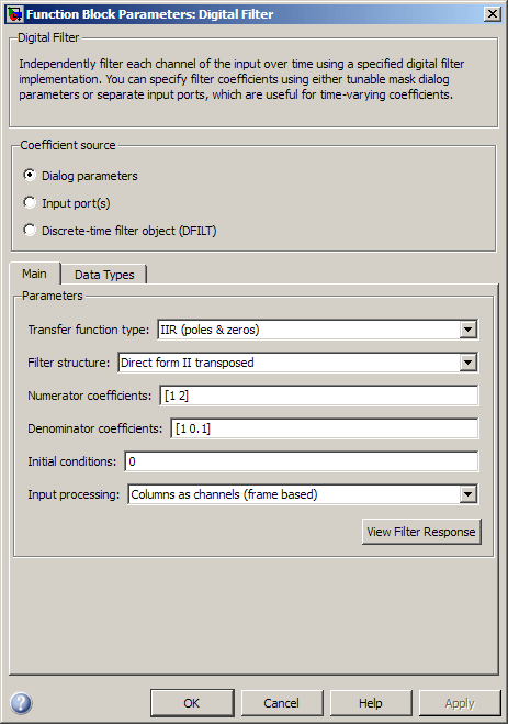
- Transfer function type
Select the type of transfer function of the filter;
IIR (poles & zeros),IIR (all poles), orFIR (all zeros). See Supported Filter Structures for more information.- Filter structure
Select the filter structure. The selection of available structures varies depending the setting of the Transfer function type parameter. See Supported Filter Structures for more information.
- Numerator coefficients
Specify the vector of numerator coefficients of the filter's transfer function.
This parameter is only visible when Dialog parameters is selected and when the selected filter structure lends itself to specification with numerator coefficients. Tunable (Simulink).
- Denominator coefficients
Specify the vector of denominator coefficients of the filter's transfer function.
In some cases, the leading denominator coefficient (a0) must be 1. See Special Consideration for the Leading Denominator Coefficient for more information.
This parameter is only visible when Dialog parameters is selected and when the selected filter structure lends itself to specification with denominator coefficients. Tunable (Simulink).
- Reflection coefficients
Specify the vector of reflection coefficients of the filter's transfer function.
This parameter is only visible when Dialog parameters is selected and when the selected filter structure lends itself to specification with reflection coefficients. Tunable (Simulink).
- SOS matrix (Mx6)
Specify an M-by-6 SOS matrix containing coefficients of a second-order section (SOS) filter, where M is the number of sections. You can use the
ss2sosandtf2sosfunctions from Signal Processing Toolbox™ software to check whether your SOS matrix is valid.This parameter is only visible when Dialog parameters is selected and when the selected filter structure is biquadratic. Tunable (Simulink).
- Scale values
Specify the scale values to be applied before and after each section of a biquadratic filter.
If you specify a scalar, that value is applied before the first filter section. The rest of the scale values are set to 1.
You can also specify a vector with M + 1 elements, assigning a different value to each scale. See Filter Structure Diagrams for diagrams depicting the use of scale values in biquadratic filter structures.
This parameter is only visible when Dialog parameters is selected and when the selected filter structure is biquadratic. Tunable (Simulink).
- First denominator coefficient = 1, remove a0 term in the structure
Select this parameter to reduce the number of computations the block must make to produce the output by omitting the
1/a0 term in the filter structure. The block output is invalid if you select this parameter when the first denominator filter coefficient is not always 1 for your time-varying filter.This parameter is only enabled when the Input port(s) is selected and when the selected filter structure lends itself to this specification.
- Coefficient update rate
Specify how often the block updates time-varying filters; once per sample or once per frame.
This parameter appears only when the following conditions are met:
You specify Input port(s) in the Coefficient source group box.
You set the Input processing parameter to
Columns as channels (frame based).
- Initial conditions
Specify the initial conditions of the filter states. To learn how to specify initial conditions, see Specifying Initial Conditions.
- Initial conditions on zeros side
(Not shown in dialog above.) Specify the initial conditions for the filter states on the side of the filter structure with the zeros (b0, b1,b2, ...); see the diagram below.
This parameter is enabled only when the filter has both poles and zeros, and when you select a structure such as direct form I, which has separate filter states corresponding to the poles (ak) and zeros (bk). To learn how to specify initial conditions, see Specifying Initial Conditions.
- Initial conditions on poles side
(Not shown in dialog above). Specify the initial conditions for the filter states on the side of the filter structure with the poles (a0, a1,a2, ...); see the diagram below.
This parameter is enabled only when the filter has both poles and zeros, and when you select a structure such as direct form I, which has separate filter states corresponding to the poles (ak) and zeros (bk). To learn how to specify initial conditions, see Specifying Initial Conditions.
- Input processing
Specify how the block should process the input. You can set this parameter to one of the following options:
Columns as channels (frame based)— When you select this option, the block treats each column of the input as a separate channel.Elements as channels (sample based)— When you select this option, the block treats each element of the input as a separate channel.
- View filter response
This button opens the Filter Visualization Tool (FVTool) from the Signal Processing Toolbox product and displays the filter response of the filter defined by the block. For more information on FVTool, see the Signal Processing Toolbox documentation.
Note
If you specify a filter in the Filter parameter, you must click the Apply button to apply the filter before using the View filter response button.
The Data Types pane of the Digital Filter block dialog appears as follows when Dialog parameters is specified in the Coefficient source group box. The parameters below can appear when Dialog parameters or Input port(s) is selected, depending on the filter structure and whether the coefficients are being entered via ports or on the block mask.
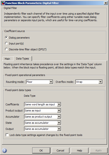
- Rounding mode
Select the rounding mode for fixed-point operations. The filter coefficients do not obey this parameter; they always round to
Nearest.- Overflow mode
Select the overflow mode for fixed-point operations. The filter coefficients do not obey this parameter; they are always saturated.
- Section I/O
Choose how you specify the word length and the fraction length of the fixed-point data type going into and coming out of each section of a biquadratic filter. See Filter Structure Diagrams for illustrations depicting the use of the section I/O data type in this block.
This parameter is only visible when the selected filter structure is biquadratic:
When you select
Same as input, these characteristics match those of the input to the block.When you select
Binary point scaling, you can enter the word and fraction lengths of the section input and output, in bits.When you select
Slope and bias scaling, you can enter the word lengths, in bits, and the slopes of the section input and output. This block requires power-of-two slope and a bias of zero.
- Tap sum
Choose how you specify the word length and the fraction length of the tap sum data type of a direct form symmetric or direct form antisymmetric filter. See Filter Structure Diagrams for illustrations depicting the use of the tap sum data type in this block.
This parameter is only visible when the selected filter structure is either
Direct form symmetricorDirect form antisymmetric:When you select
Same as input, these characteristics match those of the input to the block.When you select
Binary point scaling, you can enter the word length and the fraction length of the tap sum accumulator, in bits.When you select
Slope and bias scaling, you can enter the word length, in bits, and the slope of the tap sum accumulator. This block requires power-of-two slope and a bias of zero.
- Multiplicand
Choose how you specify the word length and the fraction length of the multiplicand data type of a direct form I transposed or biquadratic direct form I transposed filter. See Filter Structure Diagrams for illustrations depicting the use of the multiplicand data type in this block.
This parameter is only visible when the selected filter structure is either
Direct form I transposedorBiquad direct form I transposed (SOS):When you select
Same as output, these characteristics match those of the output to the block.When you select
Binary point scaling, you can enter the word length and the fraction length of the multiplicand data type, in bits.When you select
Slope and bias scaling, you can enter the word length, in bits, and the slope of the multiplicand data type. This block requires power-of-two slope and a bias of zero.
- Coefficients
Choose how you specify the word length and the fraction length of the filter coefficients (numerator and/or denominator). See Filter Structure Diagrams for illustrations depicting the use of the coefficient data types in this block:
When you select
Same word length as input, the word length of the filter coefficients match that of the input to the block. In this mode, the fraction length of the coefficients is automatically set to the binary-point only scaling that provides you with the best precision possible given the value and word length of the coefficients.When you select
Specify word length, you can enter the word length of the coefficients, in bits. In this mode, the fraction length of the coefficients is automatically set to the binary-point only scaling that provides you with the best precision possible given the value and word length of the coefficients.When you select
Binary point scaling, you can enter the word length and the fraction length of the coefficients, in bits. If applicable, you can enter separate fraction lengths for the numerator and denominator coefficients.When you select
Slope and bias scaling, you can enter the word length, in bits, and the slope of the coefficients. If applicable, you can enter separate slopes for the numerator and denominator coefficients. This block requires power-of-two slope and a bias of zero.The filter coefficients do not obey the Rounding mode and the Overflow mode parameters; they are always saturated and rounded to
Nearest.
- Product output
Use this parameter to specify how you would like to designate the product output word and fraction lengths. See Filter Structure Diagrams and Multiplication Data Types for illustrations depicting the use of the product output data type in this block:
When you select
Same as input, these characteristics match those of the input to the block.When you select
Binary point scaling, you can enter the word length and the fraction length of the product output, in bits.When you select
Slope and bias scaling, you can enter the word length, in bits, and the slope of the product output. This block requires power-of-two slope and a bias of zero.
- Accumulator
Use this parameter to specify how you would like to designate the accumulator word and fraction lengths. See Filter Structure Diagrams and Multiplication Data Types for illustrations depicting the use of the accumulator data type in this block:
When you select
Same as input, these characteristics match those of the input to the block.When you select
Same as product output, these characteristics match those of the product output.When you select
Binary point scaling, you can enter the word length and the fraction length of the accumulator, in bits.When you select
Slope and bias scaling, you can enter the word length, in bits, and the slope of the accumulator. This block requires power-of-two slope and a bias of zero.
- State
Use this parameter to specify how you would like to designate the state word and fraction lengths. See Filter Structure Diagrams for illustrations depicting the use of the state data type in this block.
This parameter is not visible for direct form and direct form I filter structures.
When you select
Same as input, these characteristics match those of the input to the block.When you select
Same as accumulator, these characteristics match those of the accumulator.When you select
Binary point scaling, you can enter the word length and the fraction length of the accumulator, in bits.When you select
Slope and bias scaling, you can enter the word length, in bits, and the slope of the accumulator. This block requires power-of-two slope and a bias of zero.
- Output
Choose how you specify the output word length and fraction length:
When you select
Same as input, these characteristics match those of the input to the block.When you select
Same as accumulator, these characteristics match those of the accumulator.When you select
Binary point scaling, you can enter the word length and the fraction length of the output, in bits.When you select
Slope and bias scaling, you can enter the word length, in bits, and the slope of the output. This block requires power-of-two slope and a bias of zero.
- Lock data type settings against changes by the fixed-point tools
Select this parameter to prevent the fixed-point tools from overriding the data types you specify on the block mask.
Specify Discrete-Time Filter Object
The Main pane of the Digital Filter block dialog appears as follows when Discrete-time filter object (DFILT) is specified in the Coefficient source group box.
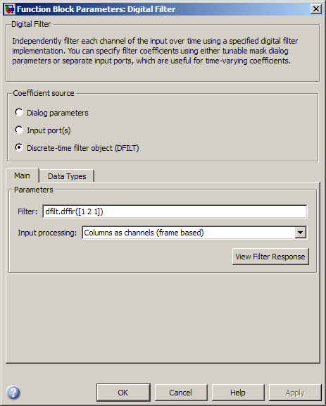
- Filter
Specify the discrete-time filter object (
dfilt) that you would like the block to implement. You can do this in one of three ways:You can fully specify the
dfiltobject in the block mask, as shown in the default value.You can enter the variable name of a
dfiltobject that is defined in any workspace.You can enter a variable name for a
dfiltobject that is not yet defined.
- Input processing
Specify how the block should process the input. You can set this parameter to one of the following options:
Columns as channels (frame based)— When you select this option, the block treats each column of the input as a separate channel.Elements as channels (sample based)— When you select this option, the block treats each element of the input as a separate channel.
- View filter response
This button opens the Filter Visualization Tool (FVTool) from the Signal Processing Toolbox product and displays the filter response of the
dfiltobject specified in the Filter parameter. For more information on FVTool, see the Signal Processing Toolbox documentation.Note
If you specify a filter in the Filter parameter, you must click the Apply button to apply the filter before using the View filter response button.
The Data Types pane of the Digital Filter block dialog appears as follows when Discrete-time filter object (DFILT) is specified in the Coefficient source group box.
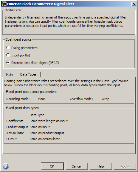
The fixed-point settings of the filter object specified on the Main pane are displayed on the Data Types pane. You cannot change these settings directly on the block mask. To change the fixed-point settings you must edit the filter object directly.
Filter Structure Diagrams
The diagrams in the following sections show the filter structures supported by the Digital Filter block. They also show the data types used in the filter structures for fixed-point signals. You can set the coefficient, output, accumulator, product output, and state data types shown in these diagrams in the block dialog. This is discussed in Dialog Box.
IIR direct form I
The following constraints are applicable when processing a fixed-point signal with this filter structure:
Inputs can be real or complex.
Numerator and denominator coefficients can be real or complex.
Numerator and denominator coefficients must be the same complexity as each other.
When the numerator and denominator coefficients are specified via input ports and have different complexities from each other, you get an error.
When the numerator and denominator coefficients are specified in the dialog and have different complexities from each other, the block does not error, but instead processes the filter as if two sets of complex coefficients are provided. The coefficient set that is real-valued is treated as if it is a complex vector with zero-valued imaginary parts.
Numerator and denominator coefficients must have the same word length. They can have different fraction lengths.
The State data type cannot be specified on the block mask for this structure, because the input and output states have the same data types as the input and output buffers.
IIR direct form I transposed
The following constraints are applicable when processing a fixed-point signal with this filter structure:
Inputs can be real or complex.
Numerator and denominator coefficients can be real or complex.
Numerator and denominator coefficients must be the same complexity as each other.
When the numerator and denominator coefficients are specified via input ports and have different complexities from each other, you get an error.
When the numerator and denominator coefficients are specified in the dialog and have different complexities from each other, the block does not error, but instead processes the filter as if two sets of complex coefficients are provided. The coefficient set that is real-valued is treated as if it is a complex vector with zero-valued imaginary parts.
States are complex when either the input or the coefficients are complex.
Numerator and denominator coefficients must have the same word length. They can have different fraction lengths.
IIR direct form II
The following constraints are applicable when processing a fixed-point signal with this filter structure:
Inputs can be real or complex.
Numerator and denominator coefficients can be real or complex.
Numerator and denominator coefficients must be the same complexity as each other.
When the numerator and denominator coefficients are specified via input ports and have different complexities from each other, you get an error.
When the numerator and denominator coefficients are specified in the dialog and have different complexities from each other, the block does not error, but instead processes the filter as if two sets of complex coefficients are provided. The coefficient set that is real-valued is treated as if it is a complex vector with zero-valued imaginary parts.
States are complex when either the inputs or the coefficients are complex.
Numerator and denominator coefficients must have the same word length. They can have different fraction lengths.
IIR direct form II transposed
The following constraints are applicable when processing a fixed-point signal with this filter structure:
Inputs can be real or complex.
Numerator and denominator coefficients can be real or complex.
Numerator and denominator coefficients must be the same complexity as each other.
When the numerator and denominator coefficients are specified via input ports and have different complexities from each other, you get an error.
When the numerator and denominator coefficients are specified in the dialog and have different complexities from each other, the block does not error, but instead processes the filter as if two sets of complex coefficients are provided. The coefficient set that is real-valued is treated as if it is a complex vector with zero-valued imaginary parts.
States are complex when either the inputs or the coefficients are complex.
Numerator and denominator coefficients must have the same word length. They can have different fraction lengths.
IIR biquadratic direct form I
The following constraints are applicable when processing a fixed-point signal with this filter structure:
Inputs and coefficients can be real or complex.
Numerator and denominator coefficients can be real or complex.
Specify the coefficients by a M-by-6 matrix in the block mask. You cannot specify coefficients by input ports for this filter structure.
When the a0 element of any row is not equal to one, that row is normalized by a0 prior to filtering.
States are complex when either the inputs or the coefficients are complex.
You cannot specify the state data type on the block mask for this structure, because the input and output states have the same data types as the input.
Scale values must have the same complexity as the coefficient SOS matrix.
The scale value parameter must be a scalar or a vector of length M+1, where M is the number of sections.
The Section I/O parameter determines the data type for the section input and output data types. The section input and stage output data type must have the same word length but can have different fraction lengths.
The following diagram shows the data types for one section of the filter.
The following diagram shows the data types between filter sections.

IIR biquadratic direct form I transposed
The following constraints are applicable when processing a fixed-point signal with this filter structure:
Inputs and coefficients can be real or complex.
Numerator and denominator coefficients can be real or complex.
Specify the coefficients by a M-by-6 matrix in the block mask. You cannot specify coefficients by input ports for this filter structure.
When the a0 element of any row is not equal to one, that row is normalized by a0 prior to filtering.
States are complex when either the inputs or the coefficients are complex.
Scale values must have the same complexity as the coefficient SOS matrix.
The scale value parameter must be a scalar or a vector of length M+1, where M is the number of sections.
The Section I/O parameter determines the data type for the section input and output data types. The section input and section output data type must have the same word length but can have different fraction lengths.
The following diagram shows the data types for one section of the filter.
The following diagram shows the data types between filter sections.
IIR biquadratic direct form II
The following constraints are applicable when processing a fixed-point signal with this filter structure:
Inputs and coefficients can be real or complex.
Numerator and denominator coefficients can be real or complex.
Specify the coefficients by a M-by-6 matrix in the block mask. You cannot specify coefficients by input ports for this filter structure.
When the a0 element of any row is not equal to one, that row is normalized by a0 prior to filtering.
States are complex when either the inputs or the coefficients are complex.
Scale values must have the same complexity as the coefficient SOS matrix.
The scale value parameter must be a scalar or a vector of length M+1, where M is the number of sections.
The Section I/O parameter determines the data type for the section input and output data types. The section input and section output data type must have the same word length but can have different fraction lengths.
The following diagram shows the data types for one section of the filter.
The following diagram shows the data types between filter sections.
IIR biquadratic direct form II transposed
The following constraints are applicable when processing a fixed-point signal with this filter structure:
Inputs and coefficients can be real or complex.
Numerator and denominator coefficients can be real or complex.
Specify the coefficients by a M-by-6 matrix in the block mask. You cannot specify coefficients by input ports for this filter structure.
When the a0 element of any row is not equal to one, that row is normalized by a0 prior to filtering.
States are complex when either the inputs or the coefficients are complex.
Scale values must have the same complexity as the coefficient SOS matrix.
The scale value parameter must be a scalar or a vector of length M+1, where M is the number of sections.
The Section I/O parameter determines the data type for the section input and output data types. The section input and section output data type must have the same word length but can have different fraction lengths.
The following diagram shows the data types for one section of the filter.
The following diagram shows the data types between filter sections.
IIR (all poles) direct form
The following constraints are applicable when processing a fixed-point signal with this filter structure:
Inputs and coefficients can be real or complex.
Denominator coefficients can be real or complex.
You cannot specify the state data type on the block mask for this structure, because the input and output states have the same data types as the input.
IIR (all poles) direct form transposed

The following constraints are applicable when processing a fixed-point signal with this filter structure:
Inputs and coefficients can be real or complex.
Denominator coefficients can be real or complex.
IIR (all poles) direct form lattice AR
The following constraints are applicable when processing a fixed-point signal with this filter structure:
Inputs and coefficients can be real or complex.
Coefficients can be real or complex.
FIR (all zeros) direct form
The following constraints are applicable when processing a fixed-point signal with this filter structure:
Inputs can be real or complex.
Numerator coefficients can be real or complex.
You cannot specify the state data type on the block mask for this structure, because the input and output states have the same data types as the input.
FIR (all zeros) direct form symmetric
The following constraints are applicable when processing a fixed-point signal with this filter structure:
Inputs can be real or complex.
Numerator coefficients can be real or complex.
You cannot specify the state data type on the block mask for this structure, because the input and output states have the same data types as the input.
It is assumed that the filter coefficients are symmetric. Only the first half of the coefficients are used for filtering.
The Tap Sum parameter determines the data type the filter uses when it sums the inputs prior to multiplication by the coefficients.
FIR (all zeros) direct form antisymmetric

The following constraints are applicable when processing a fixed-point signal with this filter structure:
Inputs can be real or complex.
Numerator coefficients can be real or complex.
You cannot specify the state data type on the block mask for this structure, because the input and output states have the same data types as the input.
It is assumed that the filter coefficients are antisymmetric. Only the first half of the coefficients are used for filtering.
The Tap Sum parameter determines the data type the filter uses when it sums the inputs prior to multiplication by the coefficients.
FIR (all zeros) direct form transposed
The following constraints are applicable when processing a fixed-point signal with this filter structure:
Inputs can be real or complex.
Coefficients can be real or complex.
States are complex when either the inputs or the coefficients are complex.
FIR (all zeros) lattice MA
The following constraints are applicable when processing a fixed-point signal with this filter structure:
Inputs and coefficients can be real or complex.
Coefficients can be real or complex.
HDL Code Generation
HDL Coder™ provides additional configuration options that affect HDL implementation and synthesized logic.
Note
Use of Digital Filter block in future releases is not recommended. Existing instances will continue to operate, but certain functionality will be disabled. We strongly recommend using Discrete FIR Filter (Simulink) or Biquad Filter in new designs.
HDL Architecture
When you specify SerialPartition and
ReuseAccum for a Digital Filter block, observe
the following constraints.
If you specify Dialog parameters as the
Coefficient source:Set Transfer function type to
FIR (all zeros).Select Filter structure as one of:
Direct form,Direct form symmetric, orDirect form asymmetric.
Distributed Arithmetic properties DALUTPartition and
DARadix are supported for the
default architecture, with FIR, Asymmetric FIR,
and Symmetric FIR filter structures.
When you use AddPipelineRegisters, registers are placed based on the filter structure. The pipeline register placement determines the latency.
| Architecture | Pipeline Register Placement | Latency (clock cycles) |
|---|---|---|
| FIR, Asymmetric FIR, and Symmetric FIR filters | A pipeline register is added between levels of a tree-based adder. | ceil(log2(FL)).
FL is the filter
length. |
| FIR Transposed | A pipeline register is added after the products. | 1 |
| IIR SOS | Pipeline registers are added between the filter sections. | NS-1.
NS is the number of
sections. |
HDL Filter Properties
| AddPipelineRegisters | Insert a pipeline register between stages of computation in a filter. See also AddPipelineRegisters (HDL Coder). |
| CoeffMultipliers | Specify the use of canonical signed digit (CSD) optimization to decrease filter area
by replacing coefficient multipliers with shift-and-add logic. When you choose a fully
parallel filter implementation, you can set CoeffMultipliers to
|
| DALUTPartition | Specify distributed arithmetic partial-product LUT partitions as a vector of the sizes of each partition. The sum of all vector elements must be equal to the filter length. The maximum size for a partition is 12 taps. Set DALUTPartition to a scalar value equal to the filter length to generate DA code without LUT partitions. See also DALUTPartition (HDL Coder). |
| MultiplierInputPipeline | Specify the number of pipeline stages to add at filter multiplier inputs. See also MultiplierInputPipeline (HDL Coder). |
| MultiplierOutputPipeline | Specify the number of pipeline stages to add at filter multiplier outputs. See also MultiplierOutputPipeline (HDL Coder). |
| ReuseAccum | Enable or disable accumulator reuse in a serial filter implementation.
Set ReuseAccum to |
HDL Block Properties
| ConstrainedOutputPipeline | Number of registers to place at
the outputs by moving existing delays within your design. Distributed
pipelining does not redistribute these registers. The default is
|
| InputPipeline | Number of input pipeline stages
to insert in the generated code. Distributed pipelining and constrained
output pipelining can move these registers. The default is
|
| OutputPipeline | Number of output pipeline stages
to insert in the generated code. Distributed pipelining and constrained
output pipelining can move these registers. The default is
|
Complex Coefficients and Data Support
Except for decimator and interpolator filter structures, HDL Coder supports use of complex coefficients and complex input signals for all filter structures of the Digital Filter block.
Restrictions
You must set Initial conditions to zero. HDL code generation is not supported for nonzero initial states.
HDL Coder does not support the Digital Filter block Input port(s) option for HDL code generation.
Supported Data Types
Double-precision floating point
Single-precision floating point
Fixed point (signed only)
8-, 16-, and 32-bit signed integers
See Also
| Allpole Filter | DSP System Toolbox |
| Digital Filter Design | DSP System Toolbox |
| Biquad Filter | DSP System Toolbox |
| Discrete Filter (Simulink) | Simulink |
| Discrete FIR Filter (Simulink) | Simulink |
| Filter Realization Wizard | DSP System Toolbox |
filterDesigner | DSP System Toolbox |
| FVTool | Signal Processing Toolbox |
Version History
Introduced in R2014b
You can also select a web site from the following list
Americas
- América Latina (Español)
- Canada (English)
- United States (English)
Europe
- Belgium (English)
- Denmark (English)
- Deutschland (Deutsch)
- España (Español)
- Finland (English)
- France (Français)
- Ireland (English)
- Italia (Italiano)
- Luxembourg (English)
- Netherlands (English)
- Norway (English)
- Österreich (Deutsch)
- Portugal (English)
- Sweden (English)
- Switzerland
- United Kingdom (English)
Asia Pacific
- Australia (English)
- India (English)
- New Zealand (English)
- 中国
- 日本Japanese (日本語)
- 한국Korean (한국어)