Sample- and Frame-Based Concepts
This topic starts by defining basic concepts such as samples and frames, sample time (also known as sample period), sample rate, frame period, and frame rate, all in the context of a Simulink® model. The topic then discusses signal generation, signal processing in the sample-based and frame-based modes, and briefly discusses the benefits of frame-based processing.
Sample Rate and Frame Rate
Samples and Frames
A sample is a value or a set of values (multichannel signal) of a signal at a given time instant. A frame is a vector or a matrix (multichannel signal) of buffered samples of consecutive times stacked together. Both frames and samples can be matrices, but in frames the first dimension is parsed as a time domain and the second dimension is parsed as channels.
Sample Time (or Sample Period)
Sample time Ts of a block is the parameter that indicates when the block produces outputs during simulation and, if appropriate, updates its internal state. Sample time is the time interval between individual samples in a frame.
Sample Rate
The sample rate of a signal is the reciprocal of the sample time (or sample period) Ts, that is, .
In most cases, when you build a Simulink model, you need to set sample rates only for the source blocks. Simulink automatically computes the appropriate sample rates for the blocks connected to the source blocks.
Frame Period and its Relationship to the Sample Period
The frame period Tf is given by the product of the sample time Ts and the frame size M, and it is represented using this equation:
Frame Rate
The frame rate of a signal is the reciprocal of the frame period Tf and can be represented using .
This diagram shows a single-channel signal with a frame size M of 4 and a frame period Tf of 1 second. The sample period Ts is therefore 1/4 or 0.25 seconds.
In most cases, the sequence sample time Ts is more important, while the frame rate is simply a consequence of the frame size that you choose for the signal. For a sequence with a given sample time, a larger frame size corresponds to a slower frame rate and vice versa.
Input and Output Sample and Frame Period
In Simulink, blocks can have different rates for their inputs and outputs (rate conversion blocks). The frame period and frame rate at the input and output of the block is calculated based on the sample time and the signal frame size. In most cases, when you build a Simulink model, you need to set sample rates for only the source blocks. Simulink automatically computes the appropriate sample rates for the blocks connected to the source blocks.
The input frame period (Tfi) of a signal is the time interval between consecutive frame inputs to a block. Similarly, the output frame period (Tfo) is the time at which the block updates the frame vector or matrix value at the output port.
More specifically, the sample time of inputs (Tsi) and outputs (Tso) are related to their respective frame periods by these equations:
where Mi and Mo are the input and output frame sizes, respectively.
Mathematically, the input frame rate is given by and the output frame rate is given by .
You can determine the frame rate of a signal using color coding and Timing Legend. For more information, see Inspect Sample and Frame Rates in Simulink. You can change the frame rate and sample rate of a signal using direct rate conversion and frame rebuffering. For examples, see Convert Sample and Frame Rates in Simulink Using Rate Conversion Blocks and Convert Sample and Frame Rates in Simulink Using Frame Rebuffering Blocks.
Variable-Size Signals and Variable Sample Rate
A signal is called a variable-size signal when its frame size M varies during simulation. As the frame period Tf of the signal is always fixed during simulation, when you use a variable-size signal, the sample time Ts and consequently the sample rate 1/Ts of the signal vary according to the equation . For an example that shows how to generate and process variable-size signals, see Lowpass Filter Variable-Size Sinusoidal Signal and Decimate Variable-Size Sinusoidal Signal.
In order to model variable sample rates in a system, use variable-size signals.
Generating Signals
Some source blocks such as the From Multimedia File block and the Signal From Workspace block can import signals from a file in a specified path or from the MATLAB® workspace. Several blocks such as the Colored Noise block and the Sine Wave block generate signals using a predefined algorithm. For a full list of blocks that generate signals in DSP System Toolbox™, see the list of blocks in the Signal Generation category. Most of these blocks can control the number of samples in each frame (column) that they generate using the Samples per frame parameter. If you set this parameter to a value greater than 1, the blocks generate signals that have more than 1 sample in each frame (column). For examples that show how to generate signals using these blocks, see Create Signals for Sample-Based Processing and Create Signals for Frame-Based Processing.
You can further process the signals generated by the blocks using several signal processing algorithm blocks in DSP System Toolbox. The processing blocks process the signal one sample at a time (sample-based processing) or one frame at a time (frame-based processing) depending on the Input processing parameter.
Sample-Based Processing and Frame-Based Processing
In the Simulink environment, you can choose to process the signal either in the sample-based mode or in frame-based mode. However, in the MATLAB environment, System objects always process frames. MATLAB does not perform sample-based processing.
The next two sections provide more details on sampled-based processing and frame-based processing.
What Is Sample-Based Processing?
In sample-based processing, blocks process signals one sample at a time. Each element of the input signal represents one sample in a distinct channel. If the input signal is a matrix, each element corresponds to the same time. For example, from a sample-based processing perspective, this 3-by-2 matrix contains the first sample in each of the six independent channels.

When you configure a block to perform sample-based processing, the block interprets a scalar input as a single-channel signal. Similarly, the block interprets an M-by-N matrix as a multichannel signal with M*N independent channels. For example, in sample-based processing, blocks interpret this sequence of 3-by-2 matrices as a six-channel signal.

What Is Frame-Based Processing?
In frame-based processing, blocks and System objects process data in frames. Each frame of data contains samples of consecutive times stacked together. Each channel is represented by a column of the input signal. For example, from a frame-based processing perspective, this 3-by-2 matrix has two channels, each containing three samples.
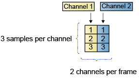
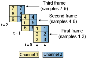
When you configure a block to perform frame-based processing, the block interprets an M-by-1 vector as a single-channel signal containing M samples per frame. Similarly, the block interprets an M-by-N matrix as a multichannel signal with N independent channels and M samples per channel. For example, in frame-based processing, blocks interpret this sequence of 3-by-2 matrices as a two-channel signal with a frame size of 3.
Benefits of Frame-Based Processing
Frame-based processing improves the simulation performance since the algorithm processes multiple samples at once reducing the overhead. It also more closely mimics how streams of signal data are handled by real-time digital signal processing systems allowing for more accurate simulations of real world behavior in hardware. For an example that compares and shows the benefits of frame-based processing in the Simulink environment, see Compare Speed Performance in Frame-Based Processing Mode Using Simulink Profiler. To perform frame-based processing, you must have a DSP System Toolbox license.
Note that frame-based processing introduces a certain amount of latency into a process due to the inherent lag in buffering the initial frame. In many instances, however, you can select frame sizes that improve throughput without creating unacceptable latencies. For more information, see Delay and Latency.
See Also
Topics
- Frame-Based Processing in Simulink
- Compare Speed Performance in Frame-Based Processing Mode Using Simulink Profiler
- Inspect Sample and Frame Rates in Simulink
- Convert Sample and Frame Rates in Simulink Using Rate Conversion Blocks
- Convert Sample and Frame Rates in Simulink Using Frame Rebuffering Blocks