Autonomous Parking Using Fuzzy Inference System
This example shows how to tune a fuzzy inference system (FIS) for an autonomous parking application with nonholonomic constraints.
Autonomous parking is an essential capability of intelligent vehicles (autonomous cars). Nonholonomic kinematics impose additional constraints on autonomous parking, where a car cannot move sideways and instead uses a curving motion.
Kinematic Model
The following figure shows the kinematics of a nonholonomic car with a standard Ackermann steering mechanism.
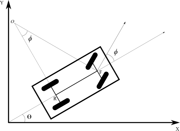
The kinematic model has the following parameters.
is the current orientation of the car with respect to a global reference frame.
is the steering angle with respect to the car orientation.
is the front wheel center, .
is the rear wheel center, .
is the length of the wheelbase.
is the center of curvature for the car.
is the radius of curvature for the car.
In this model, the rear wheel orientation is fixed and parallel to the car body. That is, the rear wheels have the same orientation as the car, . The front wheels are parallel to each other and rotate with the steering angle . The steering angle is constrained to be between and . For this example, is 30 degrees.
The front and rear wheel centers have the following relationship.
The kinematic equations for the front wheel center velocity and car orientation velocity are as follows, where is the speed of the car.
Autonomous Parking
The minimum radius of curvature () for a car depends on the wheelbase length (). This minimum radius constrains the motion of the car during parking maneuvers.
When a human driver parks, they often fail to maintain the required car speed and orientation when approaching an empty parking space. To successfully park without a collision, they must compensate by switching between forward and backward motion while adjusting the speed and steering angle of the car.
Human drivers do not consciously perform geometric computations based on the kinematic model of their car. Instead, based on their own trial-and-error experience, they use natural rules and reasoning to understand the constraints of their car within a parking situation. You can use fuzzy systems to model such rule-based reasoning.
This example uses the following environment to simulate head-on parking of a nonholonomic car.
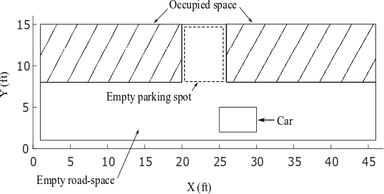
Here:
The simulation environment is a 45-by-15 foot parking lot.
The hatched area shows occupied parking spots.
The empty parking spot is of 6-by-7 feet.
The car is 5-by-3 feet and the length of the wheelbase () is 3 feet, providing a 1 foot offset from the wheelbase to both the front and rear of the car.
This example assumes the following.
The car is equipped with an intelligent system that can detect an empty parking spot and then stop the car near the starting edge of the parking spot.
The autonomous parking system takes control of the car after it stops. Ideally, at the starting position, the car is almost vertically centered in the road and parallel to the road ( deg or deg).
Due to the constantly changing nature of a parking lot, the kinematic motion constraints, and the physical car attributes, a car does stop at the exact desired position and orientation. Therefore, the parking system assumes that the car stops somewhere in front of the empty parking spot with or deg and with unequal space on either side of the car.
To avoid collisions, the car is equipped with range sensors to provide range data for the front, rear, left, and right sides of the car. The following figure shows an example of the range data obtained from the sensors in the simulation environment.
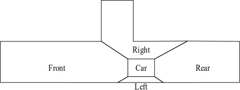
The maximum sensor range is assumed to be , which covers the entire simulation environment.
Human Reasoning for Car Parking
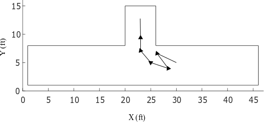
Generally, as shown in the following figure, a human driver maintains the appropriate speed and steering angle when approaching an empty head-on parking spot. In this case, they can park without any forward and backward oscillating motions.
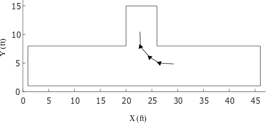
However, sometimes a driver fails to maintain the desired speed and steering angle for oscillation-free parking. As shown in the following example, the driver must then compensate using back-and-forth motions.
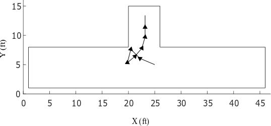
In this case, the driver:
Turns right and moves forward.
Fails to enter the parking spot, since the front of the car approaches the car in the occupied space.
Turns left and backs up to make enough room to enter the parking spot
Moves forward to enter the parking spot while adjusting the car orientation to align with the parking direction.
Stops when the front of the car is a safe minimal distance from the end of the parking spot and the vehicle is aligned with the parking spot (90 deg orientation within the simulation environment).
The following section uses these motion patterns to construct fuzzy systems for autonomous parking.
Generate Training Data
For tuning the fuzzy systems, this example artificially generates training data using the kinematic model of the car and the motion patterns described in the previous section. The data generation process uses the following discrete form of the kinematic model, where is 0.1 seconds.
The steering angle () and speed () values are generated based on the typical human driving patterns discussed previously. The steering angle and speed are constrained to the following limits.
In order to make space for safe turning, the backward motion uses a higher speed when the car gets closer to the occupied space. Alternatively, the car can use the same speed for longer periods when going backward to make adequate space for safe turning.
Load the training data structure.
trainingData = load("trainingData");Each training data point includes five inputs.
Angular deviation () between the car orientation and the parking spot orientation
Minimum distances to the front (), left (), rear (), and right () of the car
Each training data point includes two outputs.
Steering angle ()
Speed () of the car
Since the angular deviation and distance values have different units and scales, the training data is normalized to the range [0 1]. Doing so removes any sensitivity of the cost function to errors in the larger magnitude inputs. The training data structure contains both the original input and output values (x and y) and their normalized values (xn and yn).
During data generation, a successful parking condition is achieved when the car reaches a minimum safe distance from the end of the parking spot and is aligned with the parking direction.
Construct and Train Initial Fuzzy Systems
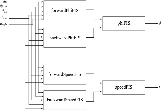
This example uses a FIS tree as the fuzzy parking system. The first stage of the tuning process is to construct and train the initial FISs that you later assemble into a FIS tree. You then improve performance by fine tuning the parameters of the entire FIS tree.
To construct and tune the initial fuzzy systems, this example uses ANFIS, which provides faster convergence compared to other tuning methods.
The design of the FIS tree and its component fuzzy systems addresses the following considerations.
The FIS tree has five inputs and two outputs that match the values in the training data set.
Since ANFIS supports a single output, construct separate fuzzy subsystems for steering angle () and speed ().
For better performance, each of these subsystems uses separate FISs for forward and backward motion.
Combine the forward and backward motion controllers for each subsystem using an additional FIS.
Train the forward motion controller for steering, forwardPhiFIS, using the training input and output data. To do so, first extract the normalized steering angle training data.
forwardPhi = trainingData.yn(:,1);
Then, since this system is only for forward motion, set the steering angle output values to 0 for negative speed values.
negSpeedId = trainingData.y(:,2) < 0;
forwardPhi(negSpeedId) = 0;
Create an initial FIS structure and specify options for ANFIS training. Use three MFs for the first input (), since it has both positive and negative values. Use two MFs for the distance inputs.
genOpt = genfisOptions("GridPartition",NumMemberShipFunctions=[3 2 2 2 2]);
initialFIS = genfis(trainingData.xn,forwardPhi,genOpt);
[in,out] = getTunableSettings(initialFIS);
opt = tunefisOptions(Method="anfis");
opt.MethodOptions.DisplayANFISInformation = false;
opt.MethodOptions.DisplayErrorValues = false;
opt.MethodOptions.DisplayStepSize = false;
opt.Display = "tuningonly";
Train forwardPhiFIS.
forwardPhiFIS = tunefis(initialFIS,[in;out],trainingData.xn,forwardPhi,opt);
Minimal training RMSE = 0.100129
In a similar manner, train the forward speed controller, forwardSpeedFIS.
forwardSpeed = trainingData.yn(:,2);
forwardSpeed(negSpeedId) = 0;

forwardSpeedFIS = tunefis(initialFIS,[in;out],trainingData.xn,forwardSpeed,opt);
Minimal training RMSE = 0.161479
Next, tune the backward motion controllers for steering angle and speed, backwardPhiFIS and backwardSpeedFIS, respectively. In this case, set the output values to 0 for positive speed values.
Train backwardPhiFIS.
backwardPhi = trainingData.yn(:,1);
backwardPhi(~negSpeedId) = 0;

backwardPhiFIS = tunefis(initialFIS,[in;out],trainingData.xn,backwardPhi,opt);
Minimal training RMSE = 0.112362
Train backwardSpeedFIS.
backwardSpeed = trainingData.yn(:,2);
backwardSpeed(~negSpeedId) = 0;

backwardSpeedFIS = tunefis(initialFIS,[in;out],trainingData.xn,backwardSpeed,opt);
Minimal training RMSE = 0.0642125
For each FIS, specify a corresponding FIS name.
forwardPhiFIS.Name = "forwardPhiFIS";
forwardSpeedFIS.Name = "forwardSpeedFIS";
backwardPhiFIS.Name = "backwardPhiFIS";
backwardSpeedFIS.Name = "backwardSpeedFIS";
Next, train phiFIS, which combines the forward and backward steering angle values generated by forwardPhiFIS and backwardPhiFIS. To generate input training data for phiFIS, evaluate forwardPhiFIS and backwardPhiFIS using the normalized input training data.
eoptions = evalfisOptions;
eoptions.EmptyOutputFuzzySetMessage = "none";
eoptions.NoRuleFiredMessage = "none";
eoptions.OutOfRangeInputValueMessage = "none";

forwardPhi = evalfis(forwardPhiFIS,trainingData.xn,eoptions);
backwardPhi = evalfis(backwardPhiFIS,trainingData.xn,eoptions);
Use five MFs for each input. In this case, you can use a higher number of MFs, since phiFIS has only two inputs.
genOpt = genfisOptions("GridPartition",NumMemberShipFunctions=5);
initialFIS2 = genfis([forwardPhi backwardPhi],trainingData.yn(:,1),genOpt);
[in2,out2] = getTunableSettings(initialFIS2);
Train phiFIS using the generated input data and the normalized output training data.
phiFIS = tunefis(initialFIS2,[in2;out2],[forwardPhi backwardPhi],trainingData.yn(:,1),opt);
Minimal training RMSE = 0.120349
phiFIS.Name = "phiFIS";Similarly, train speedFIS, which combines the forward and backward speed values generated by forwardSpeedFIS and backwardSpeedFIS, respectively. To generate input training data for speedFIS, evaluate forwardSpeedFIS and backwardSpeedFIS using the normalized input training data.
forwardSpeed = evalfis(forwardSpeedFIS,trainingData.xn,eoptions);
backwardSpeed = evalfis(backwardSpeedFIS,trainingData.xn,eoptions);

speedFIS = tunefis(initialFIS2,[in2;out2],[forwardSpeed backwardSpeed],trainingData.yn(:,2),opt);
Minimal training RMSE = 0.0956468
speedFIS.Name = "speedFIS";Construct and Tune FIS Tree
The next stage of the tuning process is to construct and tune a fuzzy tree using the previously tuned component FISs. To create the FIS tree, first define the connections between the component FISs according to the overall FIS tree design.
connections = [...
    "forwardPhiFIS/output" "phiFIS/input1"; ...
    "backwardPhiFIS/output" "phiFIS/input2"; ...
    "forwardSpeedFIS/output" "speedFIS/input1"; ...
    "backwardSpeedFIS/output" "speedFIS/input2"; ...
    "forwardPhiFIS/input1" "backwardPhiFIS/input1"; ...
    "forwardPhiFIS/input1" "forwardSpeedFIS/input1"; ...
    "forwardPhiFIS/input1" "backwardSpeedFIS/input1"; ...
    "forwardPhiFIS/input2" "backwardPhiFIS/input2"; ...
    "forwardPhiFIS/input2" "forwardSpeedFIS/input2"; ...
    "forwardPhiFIS/input2" "backwardSpeedFIS/input2"; ...
    "forwardPhiFIS/input3" "backwardPhiFIS/input3"; ...
    "forwardPhiFIS/input3" "forwardSpeedFIS/input3"; ...
    "forwardPhiFIS/input3" "backwardSpeedFIS/input3"; ...
    "forwardPhiFIS/input4" "backwardPhiFIS/input4"; ...
    "forwardPhiFIS/input4" "forwardSpeedFIS/input4"; ...
    "forwardPhiFIS/input4" "backwardSpeedFIS/input4"; ...
    "forwardPhiFIS/input5" "backwardPhiFIS/input5"; ...
    "forwardPhiFIS/input5" "forwardSpeedFIS/input5"; ...
    "forwardPhiFIS/input5" "backwardSpeedFIS/input5"; ...
    ];
Construct the FIS tree.
fuzzySystems = [...
    forwardPhiFIS backwardPhiFIS ...
    forwardSpeedFIS backwardSpeedFIS ...
    phiFIS speedFIS];
fisT = fistree(fuzzySystems,connections,Name="parkingSystem");
Next, fine-tune both the MF and rule parameter values of fisT. For better performance, tune the fuzzy system parameters for individual outputs.
First, tune the FIS parameters for steering angle.
Second, tune the FIS parameters for speed.
To tune FIS tree parameters for one output without considering the other output value, you can temporarily remove the other output from the FIS tree.
To tune the FIS tree for the steering angle output, remove the second output from fisT and get tunable settings from forwardPhiFIS, backwardPhiFIS, and phiFIS.
fisTin1 = fisT;
fisTin1.Outputs(2) = [];
[in,out,rule] = getTunableSettings(fisTin1,...
    FIS=["forwardPhiFIS" "backwardPhiFIS" "phiFIS"]);
Create a tuning option set.
toptions = tunefisOptions;
Use the patternsearch method for fine-tuning and set the maximum iteration number to 10. If you have Parallel Computing Toolbox™ software, you can improve the speed of the tuning process by setting toptions.UseParallel to true. If you do not have Parallel Computing Toolbox software, set options.UseParallel to false, which is the default value.
toptions.Method = "patternsearch";
toptions.MethodOptions.MaxIterations = 10;
To improve the pattern search results, set the method option UseCompletePoll to true.
toptions.MethodOptions.UseCompletePoll = true;
For reproducibility, set the random number generator seed to default.
rng("default")Training can be computationally intensive and take several hours to complete. To save time, load a pretrained FIS tree by setting runtunefis to false. To run the tuning, you can set runtunefis to true.
runtunefis = false;
Tune the FIS tree.
if runtunefis
    fisTout1 = tunefis(fisTin1,[in;out;rule],...
        trainingData.xn,trainingData.yn(:,1),toptions);
else
    preTunedFIST = load("tunedFIST");
    fisTout1 = preTunedFIST.fisTout1;
end
Next, tune the other FIS tree output by first removing the speed output and adding the steering angle output. Then, get tunable settings from forwardSpeedFIS, backwardSpeedFIS, and speedFIS.
fisTin2 = fisTout1;
fisTin2.Outputs(1) = "speedFIS/output";
[in,out,rule] = getTunableSettings(fisTin2,...
    FIS=["forwardSpeedFIS" "backwardSpeedFIS" "speedFIS"]);
Tune the FIS tree. After training, reset the outputs of the FIS tree.
if runtunefis
    rng("default")
    fisTout = tunefis(fisTin2,[in;out;rule],...
        trainingData.xn,trainingData.yn(:,2),toptions);
    fisTout.Outputs(1) = "phiFIS/output";
    fisTout.Outputs(2) = "speedFIS/output";
else
    fisTout = preTunedFIST.fisTout;
end
Check the individual training errors (root mean squared error) of the outputs.
err = trainingData.yn - evalfis(fisTout,trainingData.xn,eoptions);
err = err.*err;
rmsePhi = sqrt(mean(err(:,1)))
rmsePhi =
0.1186
rmseSpeed = sqrt(mean(err(:,2)))
rmseSpeed =
0.0967
The performance is not meaningfully better compared to the ANFIS-trained fuzzy system.
Autonomous Parking Simulation
The training data contains a limited set of initial conditions. Therefore, the tuned FIS tree is valid for the following conditions.
The front of the car must be initially located in front of the parking spot with .
The car must be closely aligned with the road direction, that is, the initial car orientation must be or deg.
The car must initially be at least ft from either road edge. That is, ft and ft.
Parking from Right Side
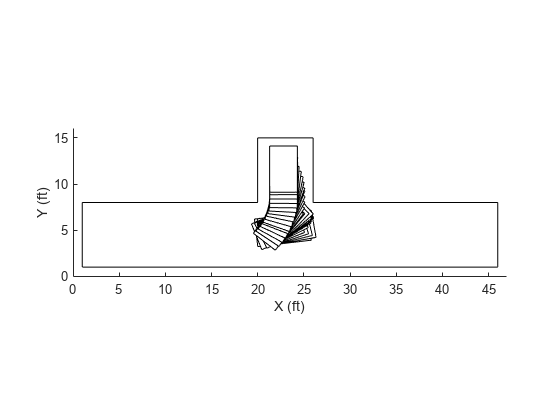
The tuned FIS is trained for head-on parking from the right side ( deg) of the road.
The following result shows a head-on parking simulation for ft, ft, and deg.
parkFromRight = true;
xf = 24;
yf = 4.5;
theta = 180;
figure
simulateParking(parkFromRight,fisTout,trainingData,xf,yf,theta)
Parked

Simulate parking for a different initial condition where ft, ft, and deg.
parkFromRight = true;
xf = 22;
yf = 5;
theta = 170;
figure
simulateParking(parkFromRight,fisTout,trainingData,xf,yf,theta)
Parked
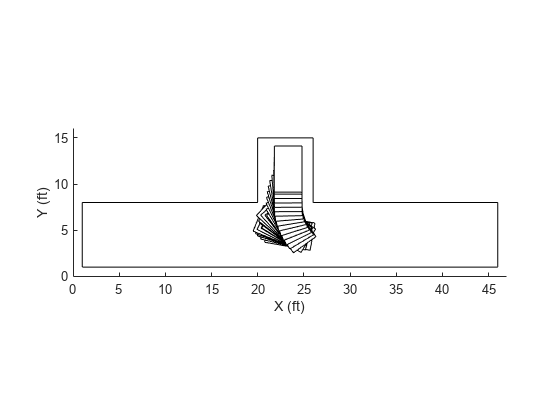
In both cases, the car can autonomously park using the back-and-forth motion pattern. However, the car does not maintain equal distance values on the left and right sides of the parking space. This behavior is common for human drivers who do not generally park in the exact middle of a parking space. Instead, they use a safe distance from each side.
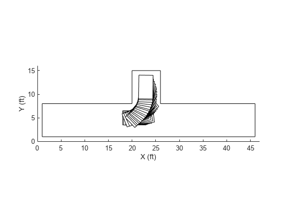
Parking from Left Side
You can use the same fuzzy system for head-on parking from the left side ( deg). To do so, set parkFromRight to false, which causes simulateParking to change the input values as follows:
Switch the sign of the angular deviation input .
Switch the distance inputs for the left () and right () sides.
Simulate autonomous parking from the left side for ft, .5 ft, and deg.
parkFromRight = false;
xf = 22;
yf = 5;
theta = 0;
figure
simulateParking(parkFromRight,fisTout,trainingData,xf,yf,theta)
Parked
Simulate parking for another initial condition where ft, .5 ft, and deg.
parkFromRight = false;
xf = 23.8;
yf = 5.2;
theta = 7;
figure
simulateParking(parkFromRight,fisTout,trainingData,xf,yf,theta)
Parked
In this case, similar to the right side parking results, the car follows a back-and-forth motion to safely park the car.
Conclusion
The current fuzzy system design has the following shortcomings:
The generated data considers only two motion patterns for autonomous parking. Therefore, the autonomous parking system has limited robustness and does not represent all common skills of a human driver. For example, the following figure shows another common scenario where the driver moves back and turns right to make space on the right from the occupied space.
The generated data uses a deg limit for steering angles. The resulting high radius of curvature increases the difficulty of parking without oscillation.
The sensor model used in this example is a trivial occupancy detection model where the range values are radially detected from the center of the car. Furthermore, when range data is similar from each corner of the car, the fuzzy system can produce unexpected results and local optima within the simulation. A better alternative is to model range data normal to each side of the car, as shown in the following figure. In this case, the distance measurements from each side of the car are independent from each other.

ANFIS supports only Sugeno FISs, which might not always produce a smooth control surface.
To update the FIS tree design, you can consider the following potential changes.
Use Mamdani FISs, which support additional tuning methods beyond ANFIS.
Design the initial rule base of the fuzzy inference systems using human reasoning and then tune with the training data.
Use a custom cost function to automatically generate data and optimize the parking trajectory using reward-based parking simulation. For an example, see Tune Fuzzy Robot Obstacle Avoidance System Using Custom Cost Function.
See Also
tunefis | tunefisOptions | fistree