Simulation Timescales
Overview to the Representation of Simulation Time
The representation of simulation time differs significantly between the HDL simulator and Simulink®. Each application has its own timing engine and the verification software must synchronize the simulation times between the two.
In the HDL simulator, the unit of simulation time is referred to as a tick. The duration of a tick is defined by the HDL simulator resolution limit. The default resolution limit is 1 ns, but may vary depending on the simulator.
ModelSim™ Users:
To determine the current ModelSim resolution limit, enter
echo $resolutionorreport simulator stateat the ModelSim prompt. You can override the default resolution limit by specifying the-toption on the ModelSim command line, or by selecting a different Simulator Resolution in the ModelSim Simulate dialog box. Available resolutions in ModelSim are 1x, 10x, or 100x in units of fs, ps, ns, us, ms, or sec. See the ModelSim documentation for further information.Xcelium™ Users:
To determine the current HDL simulator resolution limit, enter
echo $timescaleat the HDL simulator prompt. See the HDL simulator documentation for further information.Vivado® Users: Open the HDL Cosimulation block mask. You can see the value for the HDL Time Precision parameter in the Block Info tab. To change this value, you must open the Cosimulation Wizard, and regenerate the block specifying a different HDL time precision parameter in the Simulation Options pane.
Simulink maintains simulation time as a double-precision value scaled to seconds. This representation accommodates modeling of both continuous and discrete systems.
The relationship between Simulink and the HDL simulator timing affects the following aspects of simulation:
Total simulation time
Input port sample times
Output port sample times
Clock periods
During a simulation run, Simulink communicates the current simulation time to the HDL simulator at each intermediate step. (An intermediate step corresponds to a Simulink sample time hit. Upon each intermediate step, new values are applied at input ports, or output ports are sampled.)
To bring the HDL simulator up-to-date with Simulink during cosimulation, you must convert sampled Simulink time to HDL simulator time (ticks) and allow the HDL simulator to run for the computed number of ticks.
Defining the Simulink and HDL Simulator Timing Relationship
The differences in the representation of simulation time can be reconciled in one of two ways using the HDL Verifier™ interface:
By defining the timing relationship manually (with Timescales pane)
When you define the relationship manually, you determine how many femtoseconds, picoseconds, nanoseconds, microseconds, milliseconds, seconds, or ticks in the HDL simulator represent 1 second in Simulink.
By allowing HDL Verifier to define the timescale (with Timescales pane)
When you allow the software to define the timing relationship, it attempts to set the timescale factor between the HDL simulator and Simulink to be as close as possible to 1 second in the HDL simulator = 1 second in Simulink. If this setting is not possible, HDL Verifier attempts to set the signal rate on the Simulink model port to the lowest possible number of HDL simulator ticks.
Setting the Timing Mode with HDL Verifier
The Timescales pane of the HDL Cosimulation block parameters dialog box defines a correspondence between one second of Simulink time and some quantity of HDL simulator time. This quantity of HDL simulator time can be expressed in one of the following ways:
In relative terms (i.e., as some number of HDL simulator ticks). In this case, the cosimulation is said to operate in relative timing mode. The HDL Cosimulation block defaults to relative timing mode for cosimulation. For more on relative timing mode, see Relative Timing Mode.
In absolute units (such as milliseconds or nanoseconds). In this case, the cosimulation is said to operate in absolute timing mode. For more on absolute timing mode, see Absolute Timing Mode.
The Timescales pane lets you choose an optimal timing relationship between Simulink and the HDL simulator, either by entering the HDL simulator equivalent or by letting HDL Verifier calculate a timescale for you.
You can choose to have HDL Verifier calculate a timescale while you are setting the parameters on the block dialog by clicking the Timescale option then clicking Determine Timescale Now (this parameter shows as Show Times and Suggest Timescale for Vivado) or you can have HDL Verifier calculate the timescale when simulation begins by selecting Automatically determine timescale at start of simulation.
The next figure shows the default settings of the Timescales pane (example shown is for use with ModelSim).
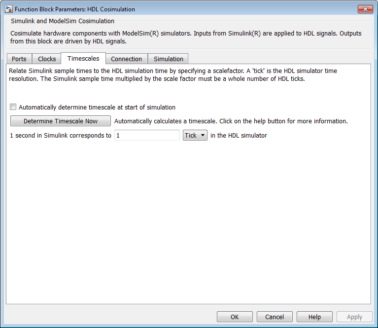
For instructions on setting the timing mode either manually or with the Timescales dialog box, see the Timescales pane in the HDL Cosimulation block reference.
Specify Timing Relationship Automatically
To have the HDL Verifier software calculate the timing relationship for you:
Start the HDL simulator. HDL Verifier software can obtain the resolution limit of the HDL simulator only when that simulator is running.
Choose to have HDL Verifier software suggest a timescale, immediately, or calculate the timescale when you start the Simulink simulation.
To have the calculation performed while you are configuring the block, on the Timescale tab, click Determine Timescale Now. The software connects Simulink with the HDL simulator so that Simulink can use the HDL simulator resolution to calculate the best timescale. The link then displays those results to you in the Timescale Details dialog box.
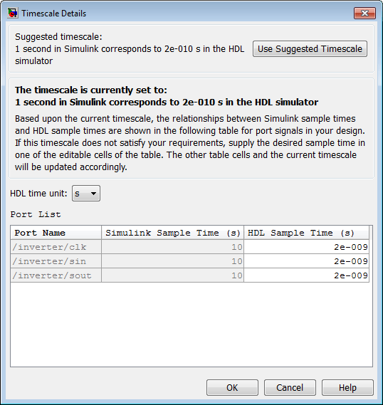
You can accept the suggested timescale, or change the port list directly:
To revert to the originally calculated settings, click Use Suggested Timescale.
To view sample times for all ports in the HDL design, select Show all ports and clocks.
To have the calculation performed when the simulation begins, select Automatically determine timescale at start of simulation, and click Apply. You obtain the same Timescale Details dialog box when the simulation starts in Simulink.
For the results to display, make sure that the HDL simulator is running and the design is loaded for cosimulation. The simulation does not have to be running.
HDL Verifier software analyzes all the clock and port signal rates from the HDL Cosimulation block when the software calculates the scale factor.
The link software returns the sample rate in either seconds or ticks:
If the results are in seconds, then the link software was able to resolve the timing differences in favor of fidelity (absolute time).
If the results are in ticks, then the link software was best able to resolve the timing differences in favor of efficiency (relative time).
Each time you select Determine Timescale Now or Automatically determine timescale at start of simulation, an interactive display opens. This display explains the results of the timescale calculations. If the link software cannot calculate a timescale for the given sample times, adjust your sample times in the Port List.
Click Apply to commit your changes.
Restrictions
HDL Verifier does not support timescales calculated automatically from frame-based signals.
HDL Verifier software cannot automatically calculate a sample timescale based on any signals driven via Tcl commands or in the HDL simulator. The link software cannot perform such calculations because it cannot know the rates of these signals.
For the results to display, make sure that the HDL simulator is running and the design is loaded for cosimulation. The simulation does not have to be running.
Relative Timing Mode
Relative timing mode defines the following one-to-one correspondence between simulation time in Simulink and the HDL simulator:
One second in Simulink corresponds
to N ticks in the HDL simulator, where N is
a scale factor. |
This correspondence holds regardless of the HDL simulator timing resolution.
The following pseudocode shows how Simulink time units are converted to HDL simulator ticks:
InTicks = N * tInSecs
where InTicks is the HDL simulator time
in ticks, tInSecs is the Simulink time in
seconds, and N is a scale factor.
Operation of Relative Timing Mode
The HDL Cosimulation block defaults to relative timing mode, with a scale factor of 1. Thus, 1 Simulink second corresponds to 1 tick in the HDL simulator. In the default case:
If the total simulation time in Simulink is specified as
Nseconds, then the HDL simulation will run for exactlyNticks (i.e.,Nns at the default resolution limit).Similarly, if Simulink computes the sample time of an HDL Cosimulation block input port as Tsi seconds, new values will be deposited on the HDL input port at exact multiples of Tsi ticks. If an output port has an explicitly specified sample time of Tso seconds, values will be read from the HDL simulator at multiples of Tso ticks.
Relative Timing Mode Example
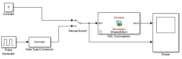
To understand how relative timing mode operates, review cosimulation results from the following example model.


Absolute Timing Mode
Absolute timing mode lets you define the timing relationship between Simulink and the HDL simulator in terms of absolute time units and a scale factor:
| One second in Simulink corresponds to (N * Tu) seconds in the HDL simulator, where Tu is an absolute time unit (for example, ms, ns, etc.) and N is a scale factor. |
In absolute timing mode, all sample times and clock periods in Simulink are quantized to HDL simulator ticks. The following pseudocode illustrates the conversion:
tInTicks = tInSecs * (tScale / tRL)
where:
tInTicksis the HDL simulator time in ticks.tInSecsis the Simulink time in seconds.tScaleis the timescale setting (unit and scale factor) chosen in the Timescales pane of the HDL Cosimulation block.tRLis the HDL simulator resolution limit.
For example, given a Timescales pane setting of 1 s and an HDL simulator resolution limit of 1 ns, an output port sample time of 12 ns would be converted to ticks as follows:
tInTicks = 12ns * (1s / 1ns) = 12
Operation of Absolute Timing Mode
To configure the Timescales parameters for absolute timing mode, you select a unit of absolute
time that corresponds to a Simulink second, rather than selecting Tick.
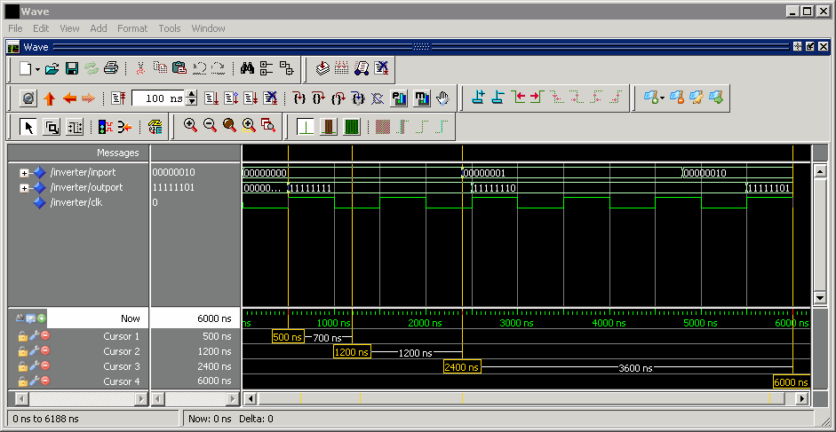
Absolute Timing Mode Example
To understand the operation of absolute timing mode, you will again consider the example model discussed in Operation of Relative Timing Mode. Suppose that the model is reconfigured as follows:
Simulation parameters in Simulink:
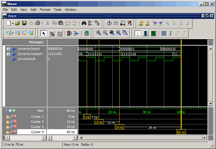
Timescale parameters:
1
s
of Simulink time corresponds to1 sof HDL simulator time.Total simulation time:
60e-9 s (60ns)Input port (
/inverter/inport) sample time:24e-9 s (24 ns)Output port (
/inverter/outport) sample time:12e-9 s (12 ns)Clock (
inverter/clk) period:10e-9 s (10 ns)
HDL simulator resolution limit:
1 ns
Given these simulation parameters, the Simulink software will cosimulate with the HDL simulator for 60 ns, during which Simulink will sample inputs at a intervals of 24 ns, update outputs at intervals of 12 ns, and drive clocks at intervals of 10 ns.
The following figure shows a ModelSim wave window after a cosimulation run.
Timing Mode Usage Considerations
When setting a timescale mode, you may need to choose your setting based on the following considerations.
Timing Mode Usage Restrictions
The following restrictions apply to the use of absolute and relative timing modes:
When multiple HDL Cosimulation blocks in a model are communicating with a single instance of the HDL simulator, all HDL Cosimulation blocks must have the same Timescales pane settings.
If you change the Timescales pane settings in an HDL Cosimulation block between consecutive cosimulation runs, you must restart the simulation in the HDL simulator.
If you specify a Simulink sample time that cannot be expressed as a whole number of HDL ticks, you will get an error.
Noninteger Time Periods
When using noninteger time periods, the HDL simulator cannot represent such an infinitely repeating value. So the simulator truncates the time period, but it does so differently than how Simulink truncates the value, and the two time periods no longer match up.
The following example demonstrates how to set the timing relationship in the following scenario: you want to use a sample period of in Simulink, which corresponds to a noninteger time period.
The key idea here is that you must always be able to relate a Simulink time with an HDL tick. The HDL tick is the finest time slice the HDL simulator recognizes; for ModelSim, the default tick is 1 ns, but it can be made as precise as 1 fs.
However, a 3 Hz signal actually has a period of 333.33333333333... ms, which is not a valid tick period for the HDL simulator. The HDL simulator will truncate such numbers. But Simulink does not make the same decision; thus, for cosimulation where you are trying to keep two independent simulators in synchronization, you should not assume anything. Instead you have to decide whether it is convenient to truncate or round the number.
Therefore, the solution is to "snap" either the Simulink sample time or the HDL sample time (via the timescale) to valid numbers. There are infinite possibilities, but here are some possible ways to perform a snap:
Change Simulink sample times from 1/3 sec to 0.33333 sec and set the cosimulation block timescale to '1 second in Simulink = 1 second in the HDL simulator'. If you are specifying a clock in the HDL Cosimulation block Clocks pane, its period should be 0.33333 sec.
Keep Simulink sample times at 1/3 sec. and 1 second in Simulink = 6 ticks in the HDL simulator.
If you are specifying a clock in the HDL Cosimulation block Clocks pane, its period should be 1/3. Briefly, this specification tells Simulink to make each Simulink sample time correspond to every (1/3*6) = 2 ticks, regardless of the HDL time resolution.
If your default HDL simulator resolution is 1 ns, that means your HDL sample times are every 2 ns. This sample time will work in a way so that for every Simulink sample time there is a corresponding HDL sample time.
However, Simulink thinks in terms of 1/3 sec periods and the HDL in terms of 2 ns periods. Thus, you could get confused during debug. If you want this to match the real period (such as to 5 places, i.e. 333.33 ms), you can follow the next option listed.
Keep Simulink sample times at 1/3 sec and 1 second in Simulink = 0.99999e9 ticks in the HDL simulator. If you are specifying a clock in the HDL Cosimulation block Clocks pane, its period should be 1/3.
Setting HDL Cosimulation Block Port Sample Times
In general, Simulink handles the sample time for the ports of an HDL Cosimulation block as follows:
If an input port is connected to a signal that has an explicit sample time, based on forward propagation, Simulink applies that rate to that input port.
If an input port is connected to a signal that does not have an explicit sample time, Simulink assigns a sample time that is equal to the least common multiple (LCM) of all identified input port sample times for the model.
After Simulink sets the input port sample periods, it applies user-specified output sample times to all output ports. Sample times must be explicitly defined for all output ports.
If you are developing a model for cosimulation in relative timing mode, consider the following sample time guideline:
Specify the output sample time for an HDL Cosimulation block as an integer
multiple of the resolution limit defined in the HDL simulator. Use the HDL
simulator command report simulator state to check the
resolution limit of the loaded model. If the HDL simulator resolution limit is 1
ns and you specify a block's output sample time as 20, Simulink interacts with the HDL simulator every 20 ns. |