HDL Cosimulation
Cosimulate HDL design by connecting Simulink with HDL simulator
Libraries:
HDL Verifier /
For Use with AMD Vivado Simulator
HDL Verifier /
For Use with Cadence Xcelium
HDL Verifier /
For Use with Siemens ModelSim/Questa
HDL Verifier /
For Use with Synopsys VCS
Description
The HDL Cosimulation block cosimulates a hardware component by applying input signals to and reading output signals from an HDL model under simulation in the HDL simulator. Configure and generate this block using the Cosimulation Wizard.
When cosimulating with the Vivado® simulator, you must first generate this block using the Cosimulation Wizard.
When cosimulating with VCS®, ModelSim™ or Xcelium™, you can optionally bypass the wizard and configure the block directly.
You can configure these options on the block:
Mapping of the input and output ports of the block to correspond with signals (including internal signals) of an HDL module. You must specify a sample time for each output port. You can optionally specify a data type for each output port. Vivado cosimulation does not support mapping of internal signals.
Type of communication and communication settings used to exchange data between simulators.
The timing relationship between units of simulation time in Simulink® and the HDL simulator.
Rising-edge or falling-edge clocks to apply to your model. You can specify the period for each clock signal.
Tcl commands to run before and after the simulation.
You can use this block to model a source or sink device by configuring the block with input or output ports only.
You can use this block in models running in normal, accelerator, or rapid accelerator simulation modes. However, when you use the Vivado simulator, the block supports only normal and rapid accelerator modes. For more information about these modes, see How Acceleration Modes Work (Simulink).
Compatibility with Simulink Code Generation
This block participates in HDL code generation with HDL Coder™. The coder generates an interface to your manually written or legacy HDL code. It does not participate in C code generation with Simulink Coder™.
Examples

Get Started with Simulink HDL Cosimulation for Synopsys VCS
Cosimulate an HDL design with Simulink and Synopsys® VCS simulator.

Verify Viterbi Decoder Using HDL Cosimulation
Generate and verify HDL code to implement a fixed-point Viterbi decoder.
Ports
The ports shown on the block correspond with signals from your HDL design running in the HDL simulator. The Ports tab displays the HDL signals that correspond to the ports.
When using Xcelium, VCS, or ModelSim simulators, You can add and remove ports, and configure their data types and sample times, by changing the block parameters. Use the Auto Fill button to fill the table via a port information request to the HDL simulator. This request returns port names and information from your HDL design running in the HDL simulator (this step is not necessary if you used the Cosimulation Wizard to generate the block). See Get Signal Information from HDL Simulator.
Note
You can only use the Auto Fill button after establishing a connection between Simulink and the HDL simulator.
All signals that you specify when you configure the HDL Cosimulation block must have read/write access in the HDL simulator. Refer to the HDL simulator product documentation for details.
Input
Output
Parameters
This parameter is read-only.
This section displays information after you generate this block using the Cosimulation Wizard. It displays the following items:
HDL Simulator – Vivado simulator
HDL Design Library – Location of HDL library files
HDL Language – VHDL or Verilog
HDL Time Precision – Time precision of HDL design
HDL Waveform File – Name and path of waveform file
When generating a cosimulation block for Vivado simulator, you cannot change the names and directions of ports, clocks, resets, or time precision using the block mask. To change these items, open the Cosimulation Wizard and regenerate the block.
Dependencies
This parameter is visible only when you use Vivado cosimulation.
Ports
Eliminates the one output-sample delay difference between the cosimulation and Simulink that occurs when your model contains purely combinational paths. Clear this check box if the HDL Cosimulation block is in a feedback loop and generates algebraic loop warnings or errors. When you simulate a sequential circuit that has a register on the data path, specifying direct feedthrough does not affect the timing of that data path.
Dependencies
Specify the signal path name using the HDL simulator path name syntax.
For example, manchester.samp for Xcelium HDL simulators. The signal can be at any level of the HDL
design hierarchy. The HDL Cosimulation block port
corresponding to the signal is labeled with this name.
For rules on specifying port and module path names in Simulink, see Specify HDL Signal/Port and Module Paths for Simulink Testbench Cosimulation.
You can copy signal path names directly from the HDL simulator
wave window and paste them into the
Full HDL Name field. Use the
Path.Name view and not
Db::Path.Name view. After pasting a
signal path name into Full HDL Name, click
Apply to complete the paste operation and
update the signal list.
Dependencies
If the block was generated from the Cosimulation Wizard, this value should not be changed. For the Vivado HDL Cosimulation block the parameter is read-only.
To add a bidirectional port, add the port to the list twice, as both input and output.
Input — HDL signals that Simulink drives. Simulink deposits values on the specified HDL simulator signal at
the specified sample rate.
Note
When you define a block input port, make sure that only one source is set up to drive input to that signal. For example, avoid defining an input port that has multiple instances. If multiple sources drive input to a single signal, your simulation model produces unexpected results.
Output — HDL signals that Simulink reads. For output signals, you must specify an explicit
sample time. You can also specify the data type, but the width must
match the width of the signal in HDL. For details on specifying a data
type, see the Data Type and Fraction
Length parameters.
Simulink signals do not have a tristate semantic because there is
no 'Z' value. To interface with bidirectional
signals, connect to the input and enable signals of both the output
driver and the output signal of the input driver. This approach leaves
the actual tristate buffer in HDL, where resolution functions can handle
interfacing with other tristate buffers.
Dependencies
If the block was generated from the Cosimulation Wizard, this value should not be changed. For the Vivado HDL Cosimulation block the parameter is read-only.
This parameter is read-only.
Displays the type of the HDL port signal, as configured by the Cosimulation Wizard.
Dependencies
This parameter is visible only if the block was generated for use with Vivado cosimulation.
This parameter is read-only.
Displays the dimensions of the HDL port signal, as configured by the Cosimulation Wizard.
Dependencies
This parameter is visible only if the block was generated for use with Vivado cosimulation.
Time interval between consecutive samples applied to an output port.
Simulink reads a value from the associated HDL simulator signal at the sample rate specified here.
In general, Simulink handles port sample periods as follows:
If you connect an input port to a signal that has an explicit sample period, based on forward propagation, Simulink applies that rate to the port.
If you connect an input port to a signal that does not have an explicit sample period, Simulink assigns a sample period that is equal to the least common multiple (LCM) of all identified input port sample periods in the model.
You must specify an explicit sample time for each output port.
The HDL time corresponding to the Simulink sample time hits depends on the Timescales setting. See Simulation Timescales.
Dependencies
To enable this parameter, set I/O Mode to
Output.
Select Inherit to automatically determine
the data type. The block checks that the inherited word length matches
the word length queried from the HDL simulator. If they do not match,
Simulink generates an error message. For example, if you connect a
Signal Specification block to an output,
Inherit forces the data type specified by
the Signal Specification block onto the output
port.
If Simulink cannot determine the data type of the signal connected to
the output port, it queries the HDL simulator for the data type of the
port. As an example, if the HDL simulator returns the VHDL® data type STD_LOGIC_VECTOR for a signal
of size N bits, the data type
ufixN is forced on the output port. The implicit
fraction length is 0.
You can also assign an explicit data type, with optional
Fraction Length. By explicitly assigning a data
type, you can force fixed-point data types on output ports of the
HDL Cosimulation block. For example, for an 8-bit
output port, setting the Sign to
Signed and setting the Fraction
Length to 5 forces the data type to
sfix8_En5. You cannot force width. The width is
always inherited from the HDL simulator.
The Data Type and Fraction Length properties apply only to the following types of HDL signals:
VHDL signals of any logic type, such as
STD_LOGICorSTD_LOGIC_VECTORVerilog® signals of
wireorregtype
Dependencies
To enable this parameter, set I/O Mode to
Output.
During cosimulation with the Vivado simulator, this parameter is displayed as Simulink Data Type.
Sign designation for explicit output port data type.
Dependencies
To enable this parameter, set I/O Mode to
Output, and set Data
Type to Fixedpoint.
Size, in bits, of the fractional part of a fixed-point output signal.
For example, for an 8-bit output port, setting the
Sign to Signed and setting
the Fraction Length to 5 forces
the data type to sfix8_En5. You cannot force width;
the width is always inherited from the HDL simulator.
Dependencies
To enable this parameter, set I/O Mode to
Output, and Data
Type property to
Fixedpoint.
The Data Type and Fraction Length properties apply only to the following types of HDL signals:
VHDL signals of any logic type, such as
STD_LOGICorSTD_LOGIC_VECTORVerilog signals of
wireorregtype
Size of the Simulink port, specified as a positive integer smaller than 129.
For input ports — this value is set
to inherit (read only).
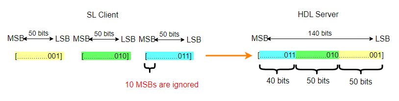
When the HDL Word Length parameter is greater than 128 bits the Simulink port dimensions are determined at compile time by the data type of the driving signal. For example:
When HDL Word Length = 150 and Simulink Word Length = 50, HDL Verifier™ allows a Simulink port with data width of 50 bits, and dimensions of size 3 such as
sfix50(3)orufix50(3).When HDL Word Length = 140 and Simulink Word Length = 50, HDL Verifier packs 150 bits of Simulink into 140 bits of HDL. HDL Verifier ignores the 10 most significant bits (MSB) of the last word.
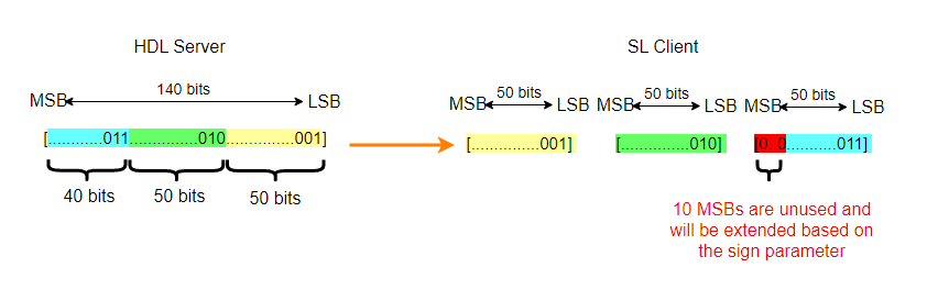
For output ports — there are 2 cases.
When the HDL Word Length parameter is less than 129 bits, this parameter matches the width of the HDL port, and it is read-only.
When the HDL Word Length parameter is greater than 128 bits, HDL Verifier creates a vector of ports to represent this port. For example:
When HDL Word Length = 150 and Simulink Word Length = 50, HDL Verifier creates a Simulink port with data width of 50 bit. For example
sfix50(3)orufix50(3).When HDL Word Length = 150 and Simulink Word Length = 60, HDL Verifier creates a Simulink port with data width of 60, such as
sfix60(3)orufix60(3). Since the HDL word has only 150 bits, and the Simulink port requires 180 bits, 30 bits are padded or sign extended.When HDL Word Length = 140 and Simulink Word Length = 50, every 50 bits of the HDL output are represented as a Simulink word. The 10 MSB of the last Simulink word are unused and extended according to the Sign parameter.
Dependencies
When HDL Word Length is smaller than 129, this parameter is read-only.
This parameter is read-only.
Size, in bits, of the HDL port.
Verilog or SystemVerilog example: In
the code below, the input In1 has an HDL word length
of 140 bits, and the output Out1 has an HDL word
length of 160 bits.
input [1:0][69:0] In1;
output [159:0] Out1;
VHDL example: In the code below,
In1 has an HDL word length of 120 bits, and
In2 has an HDL word length of 1200 bits.
TYPE matrix_of_std_logic_vector120 IS ARRAY (NATURAL RANGE <>, NATURAL RANGE <>) OF std_logic_vector(119 DOWNTO 0);
In1: IN matrix_of_std_logic_vector120(0 TO 4, 0 TO 1);
In2: IN std_logic_vector(1199 DOWNTO 0);
Clocks
Note
During cosimulation with the Vivado simulator, this tab is named Clocks, Resets, Enables.
During cosimulation with the VCS simulator, this tab is not available. Use the
PreSimulationTclproperty of thelaunchVCSfunction to define clock and reset signals.
Create optional rising-edge and falling-edge clocks that apply stimuli to your cosimulation model. The scrolling list displays HDL clocks that drive values to the HDL signals that you are modeling, using the deposit method. The clock signals must be single-bit signals. Vector signals are not supported. For instructions on adding and editing clock signals, see Creating Optional Clocks with the Clocks Pane of the HDL Cosimulation Block.
Specify the time required for the HDL simulation to run before starting the cosimulation. Specify a nonnegative integer, and select time units from the menu.
fs– Femtosecondsps– Picosecondsns– Nanosecondsus– Microsecondsms– Millisecondss– Seconds
Dependencies
To enable this parameter, generate this block for Vivado cosimulation.
Specify each clock as a signal path name, using the HDL simulator
path name syntax. For example: /manchester/clk or
manchester.clk.
For information about and requirements for path specifications in Simulink, see Specify HDL Signal/Port and Module Paths for Simulink Testbench Cosimulation.
You can copy signal path names directly from the HDL simulator
wave window and paste them into the
Full HDL Name field. Use the
Path.Name view and not
Db::Path.Name view. After pasting a
signal path name into Full HDL Name, click
Apply to complete the paste operation and
update the signal list.
Dependencies
If the block was generated from the Cosimulation Wizard, this value should not be changed. For the Vivado HDL Cosimulation block the parameter is read-only.
Select one of the following options.
Rising– Specify a rising-edge clock.Falling– Specify a falling-edge clock.
The periods and durations are Simulink times. To relate Simulink times to HDL times, go to the Timescales tab and click Determine Timescale Now.
Dependencies
This parameter is visible only for ModelSim or Xcelium cosimulation.
For Vivado cosimulation, select one of the following options.
Active Rising Edge Clock– Create a periodic signal with 50% duty cycle where the rising edge is offset from when Simulink drives the inputs.Active Falling Edge Clock– Create a periodic signal with 50% duty cycle where the falling edge is offset from when Simulink drives the inputs.Step 0 to 1– Create a step function that starts by driving a 0 for the specified duration, then transitions to 1.Step 1 to 0– Create a step function that starts by driving a 1 for the specified duration, then transitions to 0.
The periods and durations are Simulink times. To relate Simulink times to HDL times, go to the Timescales tab and click Show Times and Suggest Timescale.
Dependencies
This parameter is visible only for Vivado cosimulation.
To specify an explicit clock period, enter a sample time equal to or greater than two resolution units (ticks).
If the clock period is not an even integer, Simulink cannot create a 50% duty cycle. Instead, the HDL Verifier software creates the falling edge at
clockperiod/2 (rounded down to the nearest
integer).
For ModelSim or Xcelium periods and durations are specified as Simulink time, and for Vivado they are specified as HDL time.
Dependencies
This property is not available for cosimulation with VCS.
Timescales
Choose a timing relationship between Simulink and the HDL simulator, either manually or automatically. These parameters specify a correspondence between one second of Simulink time and some quantity of HDL simulator time. This quantity of HDL simulator time can be expressed in one of the following ways:
Relative timing relationship (Simulink seconds correspond to an HDL simulator precision, or "tick".
Absolute timing relationship (Simulink seconds correspond to an absolute unit of HDL simulator time)
For more information on calculating relative and absolute timing modes, see Defining the Simulink and HDL Simulator Timing Relationship.
For detailed information on the relationship between Simulink and the HDL simulator during cosimulation, and on the operation of relative and absolute timing modes, see Simulation Timescales.
To see the relationship between the Simulink times and HDL times of all of the ports, clocks, resets, and enables click Show Times and Suggest Timescale. This action also automatically determines a usable timescale if needed.
If you select this option, HDL Verifier calculates the timescale when you start the Simulink simulation. If this option is not selected, click Determine Timescale Now to calculate the timescale immediately without starting a simulation. For Vivado cosimulation, this button shows as Show Times and Suggest Timescale. Alternatively, you can manually select a timescale. For guidance through the automatic timescale calculation, see Specify Timing Relationship Automatically.
Dependencies
For VCS cosimulation, this parameter is disabled. You can click Show Timescale after establishing a connection between VCS and Simulink to open a dialog box with port time mapping information. For more information about starting a VCS cosimulation, see Start VCS from MATLAB.
This parameter consists of a Time value and a TimeUnit value.
To configure relative timing mode for a cosimulation:
Verify that
Tick, the default setting for TimeUnit, is selected. If it is not, then select it from the list on the right.Enter a scale factor in the Time text box on the left. The default scale factor is 1.
To configure absolute timing mode for a cosimulation:
Set TimeUnit to a unit of absolute time:
fs(femtoseconds),ps(picoseconds),ns(nanoseconds),us(microseconds),ms(milliseconds), ors(seconds).Enter a scale factor in the Time text box on the left. The default scale factor is 1.
Connection
This tab is not visible during cosimulation with the Vivado simulator.
Type of connection between Simulink and the HDL simulator.
Full Simulation: Confirm interface and run HDL simulation.Confirm Interface Only: Connect to the HDL simulator and check for signal names, dimensions, and data types, but do not run HDL simulation. During Simulink simulation, there is no contact with the HDL simulator.No Connection: Do not communicate with the HDL simulator. The HDL simulator does not need to be started.
When both applications run on the same computer, you can choose shared memory or TCP sockets for the communication channel between the applications. If you do not select this option, only TCP/IP socket mode is available, and the Connection method list becomes unavailable.
Dependencies
For VCS cosimulation, this parameter is disabled.
Socket: Simulink and the HDL simulator communicate via a designated TCP/IP socket. TCP/IP socket mode is more versatile. You can use it for single-system and network configurations. This option offers the greatest scalability. For more on TCP/IP socket communication, see TCP/IP Socket Ports.Shared memory: Simulink and the HDL simulator communicate via shared memory. Shared memory communication provides optimal performance and is the default mode of communication.
Dependencies
This parameter shows when you select HDL Simulator is running on this computer.
VCS cosimulation supports only socket communication.
This parameter applies if you run Simulink and the HDL simulator on different computers.
Dependencies
For VCS cosimulation, this parameter is read-only.
Indicate a valid TCP socket port number or service for your computer system, if you are not using shared memory. For information on choosing TCP socket ports, see TCP/IP Socket Ports.
When you select this option, the HDL Cosimulation block
icon displays the current communication parameter settings. If you
select shared memory, the icon displays SharedMem. If
you select TCP socket communication, the icon displays
Socket and displays the host name and port number
in the format hostname:port.
This information can help you distinguish between multiple HDL Cosimulation blocks, where each block is communicating to a different instance of the HDL simulator.
Simulation
This tab is not visible during cosimulation with the Vivado simulator.
Specifies the amount of time to run the HDL simulator before beginning simulation in Simulink. Specifying this time properly aligns the signal of the Simulink block and the HDL signal so that they can be compared and verified directly without additional delays.
This setting consists of a PreRunTime value and a PreRunTimeUnit value.
PreRunTime: Any valid time value. The default is 0.
PreRunTimeUnit: Specifies the units of time for PreRunTime.
Ticksmsusnspsfs
The cosimulation tool executes these commands in the HDL simulator, before simulating the HDL component of your Simulink model. If you enter multiple commands on one line, append each command with a semicolon (;), the standard Tcl concatenation operator.
For example, use this parameter to generate a one-line echo command to confirm that a simulation is running, or a complex script that performs an extensive simulation initialization and startup sequence. You cannot use these commands to change simulation state.
You can specify any valid Tcl command. The Tcl command you specify
cannot include commands that load an HDL simulator project or modify
simulator state. For example, the character vector cannot include
commands such as start, stop, or
restart (for ModelSim) or run, stop, or
reset (for Xcelium).
Dependencies
For VCS cosimulation, this parameter is disabled. Use the
PreSimulationTcl property of the launchVCS function to define pre-simulation Tcl
commands.
The cosimulation tool executes these commands in the HDL simulator, after simulating the HDL component of your Simulink model.
You can specify any valid Tcl command. The Tcl command you specify
cannot include commands that load an HDL simulator project or modify
simulator state. For example, the string cannot include commands such as
start, stop, or
restart (for ModelSim) or run, stop, or
reset (for Xcelium).
Note
After each ModelSim simulation, the simulator takes time to update the coverage result. To prevent the potential conflict between this process and the next cosimulation session, add a short pause between each successive simulation.
Dependencies
For VCS cosimulation, this parameter is disabled. Use the
PostSimulationTcl property of the launchVCS function to define post-simulation Tcl
commands.