Design Current and Position Scaling Subsystems
Use these steps to design the current and position scaling subsystems:
Create the current scaling subsystem.

This subsystem reads the current in ADC counts and converts it to per-unit (PU) values.
In this subsystem, the IaOffset and IbOffset Data Store Memory blocks are the ADC offsets for current measurement and they are hardware specific. The file
mcb.getInverterParameters.mcontains the default ADC offset (CtSensAOffset and CtSensBOffset) for few commercially available inverters. For details about ADC offset calibration in hardware, see Run 3-Phase AC Motors in Open-Loop Control and Calibrate ADC Offset.In this subsystem, the motor phase current measured in ADC counts is converted to current in PU. The
PU_System.I_basevalue refers to the base current in this subsystem. For details about the PU system, see Per-Unit System.You can use the base values for computing the real-world values from per-unit. To implement the real-world or SI unit values, see the model
mcb_pmsm_foc_qep_f28379d_SIUnitused in the example Field-Oriented Control of PMSM Using SI Units.The IaOffset and IbOffset Data Store Memory blocks are used to share data between the current and position subsystems.
Create the position scaling subsystem.

This subsystem reads the rotor position from the QEP pulse count.
In this subsystem, the Quadrature Decoder block reads the position count from the plant model or hardware driver block. The block converts the rotor mechanical position in encoder position counts to rotor mechanical angle in PU (
0-1).The Mechanical to Electrical Position (Mech2Elec Position) block adjusts the rotor mechanical angle for QEP offset (that you can provide using block parameters dialog box or via input port) and converts it to electrical angle. The FOC algorithm needs the rotor electrical angle to run the motor. To calculate the QEP encoder offset, see Quadrature Encoder Offset Calibration for PMSM.
The Speed Measurement block calculates speed from the rotor position. In the Speed Measurement block parameters dialog box, set the Delays for speed calculation (number of samples) parameter to
20. We selected the value20in this workflow so that the block can measure the maximum speed of the motor that is under test. The Speed Measurement block outputs the speed in PU.
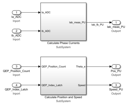
The resulting two subsystems (Calculate Phase Currents and Calculate Position and Speed) contain the current scaling and position decoding logic.