phased.ScenarioViewer
Display motion of radars and targets
Description
The phased.ScenarioViewer
System object™ creates a 3-D viewer to display the motion of radars and targets that you model
in your radar simulation. You can display current positions and velocities, object tracks,
position and speed annotations, radar beam directions, and other object parameters. You can
change radar features such as beam range and beam width during the simulation. You can use the
phased.Platform
System object to model moving objects or you can supply your own dynamic models.
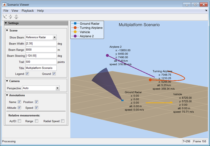
This figure shows a four-object scenario consisting of a ground radar, two airplanes, and a ground vehicle. You can view the code that generated this figure in the Visualize Multiplatform Scenario example.

To run the scenario viewer:
Create the
phased.ScenarioViewerobject and set its properties.Call the object with arguments, as if it were a function.
To learn more about how System objects work, see What Are System Objects?
Creation
Description
creates a
scenario viewer System object, sIS = phased.ScenarioViewersIS having default property values.
returns a scenario viewer System object, sIS = phased.ScenarioViewer(Name=Value)sIS, with any specified property
Name set to a specified Value.
Name must appear inside double quotes (""). You
can specify several name-value pair arguments in any order as
Name1=Value1,...,NameN=ValueN. For example, to specify a beamwidth of
15, set BeamWidth=15.
Properties
Unless otherwise indicated, properties are nontunable, which means you cannot change their
values after calling the object. Objects lock when you call them, and the
release function unlocks them.
If a property is tunable, you can change its value at any time.
For more information on changing property values, see System Design in MATLAB Using System Objects.
Window caption name, specified as a character vector. The Name
property and the Title property are different.
Example: "Multitarget Viewer"
Data Types: char
Reference radar index, specified as a positive integer. This property selects one of
the radars as the reference radar. Its value must be less than or equal to the number of
radars that you specify in the radar_pos argument of the object.
This property is tunable. Target range, radial speed, azimuth, and elevation are defined
with respect to this radar.
Example: 2
Data Types: double
Enable the display of radar beams, specified as "ReferenceRadar",
"None", or "All". This option determines which
radar beams to show.
| Option | Beams to show |
|---|---|
"ReferenceRadar" | Show the beam of the radar specified in the
ReferenceRadar property. |
"None" | Do not show any radar beams. |
"All" | Show the beams for all radars. |
This property is tunable.
Example: "All"
Data Types: char
Vertical and horizontal radar beam widths, specified as a positive real-valued scalar, a 2-element column vector, an N-element row vector, or a 2-by-N matrix. N is the number of radars. All scalar, vector, and matrix entries are positive, real-valued numbers between 0–360°. Units are in degrees.
| Value Specification | Interpretation |
|---|---|
| Scalar | The horizontal and vertical radar beam widths are equal and identical for all radars. |
| 2-element column vector | The first row specifies the horizontal beam width. The second row specifies the vertical beam width. These values are identical for all radars. |
| N-element row vector | Each element applies to one radar. Vertical and horizontal beam widths for each radar are equal. |
| 2-by-N matrix | Each column applies to one radar. The first row specifies the horizontal beam width and the second row specifies the vertical beam width for each radar. |
When CameraPerspective is set to "Radar",
the System object uses this property to calculate the value of
CameraViewAngle. This property is tunable.
Example: [20 10; 18 9]
Data Types: double
Radar beam range, specified as a positive scalar or an N-element row vector, where N is the number of radars. Units are in meters. When specified as a scalar, all radars have the same beam range. When specified as a vector, each element corresponds to one radar. This property is tunable.
Example: [1000 1500 850]
Data Types: double
Beam steering directions of radars, specified as a real-valued 2-element column
vector of positive values or 2-by-N real-valued matrix of positive
values. N is the number of radars. Beam steering angles are relative
to the local coordinate axes of each radar. Units are in degrees. Each column takes the
form [azimuthangle;elevationangle]. When only one column is
specified, the beam steering directions of all radars are the same. Azimuth angles are
from –180° to 180°, and the elevation angles are from –90° to 90°.
This property is tunable.
Example: [20 60 35; 5 0 10]
Data Types: double
Enable the velocity input arguments, radar_velocity and
tgt_velocity, of the object, specified as true
or false. Setting this property to true enables
the input arguments. When this property is false, velocity vectors
are estimated from the position change between consecutive updates divided by the update
interval. The update interval is the inverse of the UpdateRate
value.
Example: false
Data Types: logical
Enable the input of local coordinate system orientation axes,
radar_laxes and tgt_laxes, to the object,
specified as false or true. Setting this property
to true enables the input arguments. When this property is
false, the orientation axes are aligned with the global coordinate
axes.
Example: true
Data Types: logical
Update rate of scenario viewer, specified as a positive scalar. Units are in hertz.
Example: 2.5
Data Types: double
Display title, specified as a character vector. The Title
property and the Name property are different. The display title
appears within the figure at the top. The name appears at the top of the figure window.
This property is tunable.
Example: "Radar and Target Display"
Data Types: char
Names assigned to radars and targets, specified as a 1-by-(N+M)
cell array of character vectors. N is the number of radars and
M is the number of targets. Order the cell entries by radar names,
followed by target names. Names appear in the legend and annotations. When you set
PlatformNames to "Auto", names are created
sequentially starting from "Radar 1" for radars and "Target
1" for targets.
Example: {'Stationary Radar','Mobile
Radar','Airplane'}
Data Types: cell
Length of the visibility of object tracks, specified as a positive integer or
(N+M)-length vector of positive integers. N is
the number of radars and M is the number of targets. When
TrailLength is a scalar, all tracks have the same length. When
TrailLength is a vector, each element of the vector specifies the
length of the corresponding radar or target trajectory. Order the entries by radars,
followed by targets. Each call to the object generates a new visible point. This
property is tunable.
Example: [100,150,100]
Data Types: double
Camera perspective, specified as "Auto",
"Custom", or "Radar". When you set this property
to "Auto", the System object estimates appropriate values for the camera position, orientation, and
view angle to show all tracks. When you set this property to
"Custom", you can set the camera position, orientation, and angles
using camera properties or the camera toolbar. When you set this property to
"Radar", the System object determines the camera position, orientation, and angles from the radar
position and the radar beam steering direction. This property is tunable.
Example: "Radar"
Data Types: char
Camera position, specified as an [x,y,z] vector of real values.
Units are in meters. This property applies when you set
CameraPerspective to "Custom". When you do not
specify this property, the System object chooses values based on your display configuration. This property is
tunable.
Example: [100,50,40]
Data Types: double
Camera orientation, specified as a [pan,tilt,roll] vector of
positive, real values. Units are in degrees. Pan and roll angles take values from
–180° to 180°. The tilt angle takes
values from –90° to 90°. Camera
rotations are performed in the order: pan, tilt, and roll. This property applies when
you set CameraPerspective to "Custom". When you
do not specify this property, the System object chooses values based on your display configuration. This property is
tunable.
Example: [180,45,30]
Data Types: double
Camera view angle, specified as a real-valued scalar. Units are in degrees. View
angle values are in the range 0° to 360°. This property applies when you set
CameraPerspective to "Custom". When you do not
specify this property, the System object chooses values based on your display configuration. This property is
tunable.
Example: 75
Data Types: double
Option to show the viewer legend, specified as false or
true. This property is tunable.
Example: true
Data Types: logical
Option to show the ground plane of the viewer scenario, specified as
true or false. This property is tunable.
Example: false
Data Types: logical
Annotate radar and target tracks with names, specified as true or
false. You can define custom platform names using
PlatformNames. This property is tunable.
Example: false
Data Types: logical
Option to annotate radar and target tracks with positions, specified as
false or true. This property is tunable.
Example: true
Data Types: logical
Option to annotate radar and target tracks with the range from the reference radar,
specified as false or true. This property is
tunable.
Example: true
Data Types: logical
Option to annotate radar and target tracks with altitude, specified as
false or true. This property is tunable.
Example: true
Data Types: logical
Option to annotate radar and target tracks with speed, specified as
false or true. This property is tunable.
Example: true
Data Types: logical
Option to annotate radar and target tracks with radial speed, specified as
false or true. Radial speed is relative to the
reference radar. This property is tunable.
Example: true
Data Types: logical
Option to annotate radar and target tracks with azimuth and elevation angles
relative to the reference radar, specified as false or
true. This property is tunable.
Example: true
Data Types: logical
Scenario viewer window size and position, specified as a [left bottom width
height] vector of positive, real values. Units are in pixels.
leftsets the position of the left edge of the window.bottomsets the position of the bottom edge of the window.widthsets the width of the window.heightsets the height of the window.
When you do not specify this property, the window is positioned at the
center of the screen, with width and height taking
the values 410 and 300 pixels, respectively. This
property is tunable.
Example: [100,200,800,500]
Data Types: double
Option to reduce the plot rate to improve performance, specified as
true or false. Set this property to
true to update the viewer at a reduced rate. Set this property to
false to update the viewer with each call to the object. This mode
adversely affects viewer performance. This property is tunable.
Example: false
Data Types: logical
Usage
Syntax
Description
sSV(
also specifies the radar velocity, radar_pos,tgt_pos,radar_velocity,tgt_velocity)radar_velocity, and target
velocity, tgt_velocity. This syntax applies when
VelocityInputPort is set to true and
OrientationInputPort is set to false.
sSV(
also specifies the radar orientation axes, radar_pos,radar_laxes,tgt_pos,tgt_laxes)radar_laxes, and the
target orientation axes, tgt_laxes. This syntax applies when
VelocityInputPort is set to false and
OrientationInputPort is set to true.
sSV(
also specifies velocity and orientation axes when radar_pos,radar_velocity,radar_laxes,tgt_pos,tgt_velocity,tgt_laxes)VelocityInputPort
and OrientationInputPort are set to true.
Input Arguments
Radar positions, specified as a real-valued 3-by-N matrix.
N is the number of radar tracks and must be equal to or greater
than one. Each column has the form [x;y;z]. Position units are in
meters.
Example: [100,250,75;0,20,49;300,5,120]
Data Types: double
Target positions, specified as a real-valued 3-by-N matrix.
M is the number of target tracks and must be equal to or greater
than one. Each column has the form [x;y;z]. Position units are in
meters.
Example: [200,40;10,40;305,15]
Data Types: double
Radar velocities, specified as a real-valued 3-by-N matrix.
N is the number of radar tracks and must be equal to or greater
than one. Each column has the form [vx;vy;vz]. The dimensions of
radar_velocity must match the dimensions of
radar_pos. Velocity units are in meters per second.
Example: [100,10,0;4,0,7;100,500,0]
Data Types: double
Target velocities, specified as a real-valued 3-by-M matrix.
M is the number of target tracks and must be equal to or greater
than one. Each column has the form [vx;vy;vz]. The dimensions of
tgt_velocity must match the dimensions of
target_position. Velocity units are in meters per
second.
Example: [100,10,0;4,0,7;100,500,0]
Data Types: double
Local coordinate axes of radar, specified as a real-valued 3-by-3-by-N array. N is the number of radar tracks. Each page (third index) represents a 3-by-3 orthogonal matrix that specifies the local coordinate axes of one radar. The columns are the unit vectors that form the x, y, and z axes of the local coordinate system. Array units are dimensionless.
Example: [100,10,0;4,0,7;100,500,0]
Data Types: double
Local coordinate axes of target, specified as a real-valued 3-by-3-by-M array. M is the number of target tracks. Each page (third index) represents a 3-by-3 orthogonal matrix that specifies the local coordinate axes of one radar. The columns are the unit vectors that form the x, y, and z axes of the local coordinate system. Array units are dimensionless.
Example: [100,10,0;4,0,7;100,500,0]
Data Types: double
Object Functions
To use an object function, specify the
System object as the first input argument. For
example, to release system resources of a System object named obj, use
this syntax:
release(obj)
Examples
Visualize the tracks of a radar and a single airplane target. The radar is stationary and the airplane is moving in a straight line. Maintain the radar beam pointing at the airplane.
Create the radar and airplane platform System objects™. Set the update rate to 0.1 s.
updateRate = 0.1; radarPlatform = phased.Platform(... InitialPosition=[0;0;10], ... Velocity=[0;0;0]); airplanePlatforms = phased.Platform(... InitialPosition=[5000.0;3500.0;6000.0], ... Velocity=[-300;0;0]);
Create the phased.ScenarioViewer System object. Show the radar beam and annotate the tracks with position, speed, and altitude.
sSV = phased.ScenarioViewer(BeamRange=5000.0,UpdateRate=updateRate,... PlatformNames={'Ground Radar','Airplane'},ShowPosition=true,... ShowSpeed=true,ShowAltitude=true,ShowLegend=true);
Run the scenario. At each step, compute the angle to the target. Use that angle to steer the radar beam toward the target.
for i = 1:100 [radar_pos,radar_vel] = radarPlatform(updateRate); [tgt_pos,tgt_vel] = airplanePlatforms(updateRate); [rng,ang] = rangeangle(tgt_pos,radar_pos); sSV.BeamSteering = ang; step(sSV,radar_pos,radar_vel,tgt_pos,tgt_vel); pause(0.1); end

Visualize the tracks of an airborne radar and a ground vehicle target. The airborne radar is carried by a drone flying at an altitude of 5 km.
Create the drone radar and ground vehicle using phased.Platform System objects™. Set the update rate to 0.1 s.
updateRate = 0.1; drone = phased.Platform(... "InitialPosition",[100;1000;5000], ... "Velocity",[400;0;0]); vehicle = phased.Platform(MotionModel="Acceleration", ... InitialPosition=[5000.0;3500.0;0.0],... InitialVelocity=[40;5;0],Acceleration=[0.1;0.1;0]);
Create the phased.ScenarioViewer System object. Show the radar beam and annotate the tracks with position, speed, and altitude.
viewer = phased.ScenarioViewer(BeamRange=8000.0, BeamWidth=2,UpdateRate=updateRate, ... PlatformNames={'Drone Radar','Vehicle'},ShowPosition=true, ... ShowSpeed=true,ShowAltitude=true,ShowLegend=true,Title="Vehicle Tracking Radar");
Run the scenario. At each step, compute the angle to the target. Use that angle to steer the radar beam toward the target.
for i = 1:100 [radar_pos,radar_vel] = drone(updateRate); [tgt_pos,tgt_vel] = vehicle(updateRate); [rng,ang] = rangeangle(tgt_pos,radar_pos); viewer.BeamSteering = ang; viewer(radar_pos,radar_vel,tgt_pos,tgt_vel) pause(.1) end

This example shows how to create and display a multiplatform scenario containing a ground-based stationary radar, a turning airplane, a constant-velocity airplane, and a moving ground vehicle. The turning airplane follows a parabolic flight path while descending at a rate of 20 m/s.
Specify the scenario refresh rate at 0.5 Hz. For 150 steps, the time duration of the scenario is 300 s.
updateRate = 0.5; N = 150;
Set up the turning airplane using the Acceleration model of the phased.Platform System object™. Specify the initial position of the airplane by range and azimuth from the ground-based radar and its elevation. The airplane is 10 km from the radar at 60° azimuth and has an altitude of 6 km. The airplane is accelerating at 10 m/s² in the negative x-direction.
airplane1range = 10.0e3; airplane1Azimuth = 60.0; airplane1alt = 6.0e3; airplane1Pos0 = [cosd(airplane1Azimuth)*airplane1range;... sind(airplane1Azimuth)*airplane1range;airplane1alt]; airplane1Vel0 = [400.0;-100.0;-20]; airplane1Accel = [-10.0;0.0;0.0]; airplane1platform = phased.Platform(MotionModel="Acceleration", ... AccelerationSource="Input port",InitialPosition=airplane1Pos0,... InitialVelocity=airplane1Vel0,OrientationAxesOutputPort=true,... InitialOrientationAxes=eye(3));
Set up the stationary ground radar at the origin of the global coordinate system. To simulate a rotating radar, change the ground radar beam steering angle in the processing loop.
groundRadarPos = [0,0,0]'; groundRadarVel = [0,0,0]'; groundradarplatform = phased.Platform(MotionModel="Velocity", ... InitialPosition=groundRadarPos,Velocity=groundRadarVel, ... InitialOrientationAxes=eye(3));
Set up the ground vehicle to move at a constant velocity.
groundVehiclePos = [5e3,2e3,0]'; groundVehicleVel = [50,50,0]'; groundvehicleplatform = phased.Platform(MotionModel="Velocity",... InitialPosition=groundVehiclePos,Velocity=groundVehicleVel,... InitialOrientationAxes=eye(3));
Set up the second airplane to also move at constant velocity.
airplane2Pos = [8.5e3,1e3,6000]'; airplane2Vel = [-300,100,20]'; airplane2platform = phased.Platform(MotionModel="Velocity", ... InitialPosition=airplane2Pos,Velocity=airplane2Vel, ... InitialOrientationAxes=eye(3));
Set up the scenario viewer. Specify the radar as having a beam range of 8 km, a vertical beam width of 30°, and a horizontal beam width of 2°. Annotate the tracks with position, speed, altitude, and range.
BeamSteering = [0;50]; viewer = phased.ScenarioViewer(BeamRange=8.0e3,BeamWidth=[2;30],UpdateRate=updateRate, ... PlatformNames={'Ground Radar','Turning Airplane','Vehicle','Airplane 2'},ShowPosition=true, ... ShowSpeed=true,ShowAltitude=true,ShowLegend=true,ShowRange=true, ... Title="Multiplatform Scenario",BeamSteering=BeamSteering);
Step through the display processing loop, updating radar and target positions. Rotate the ground-based radar steering angle by four degrees at each step.
for n = 1:N [groundRadarPos,groundRadarVel] = groundradarplatform(updateRate); [airplane1Pos,airplane1Vel,airplane1Axes] = airplane1platform(updateRate,airplane1Accel); [vehiclePos,vehicleVel] = groundvehicleplatform(updateRate); [airplane2Pos,airplane2Vel] = airplane2platform(updateRate); viewer(groundRadarPos,groundRadarVel,[airplane1Pos,vehiclePos,airplane2Pos],... [airplane1Vel,vehicleVel,airplane2Vel]); BeamSteering = viewer.BeamSteering(1); BeamSteering = mod(BeamSteering + 4,360.0); if BeamSteering > 180.0 BeamSteering = BeamSteering - 360.0; end viewer.BeamSteering(1) = BeamSteering; pause(0.2); end

Version History
Introduced in R2016a
MATLAB Command
You clicked a link that corresponds to this MATLAB command:
Run the command by entering it in the MATLAB Command Window. Web browsers do not support MATLAB commands.
Sélectionner un site web
Choisissez un site web pour accéder au contenu traduit dans votre langue (lorsqu'il est disponible) et voir les événements et les offres locales. D’après votre position, nous vous recommandons de sélectionner la région suivante : .
Vous pouvez également sélectionner un site web dans la liste suivante :
Comment optimiser les performances du site
Pour optimiser les performances du site, sélectionnez la région Chine (en chinois ou en anglais). Les sites de MathWorks pour les autres pays ne sont pas optimisés pour les visites provenant de votre région.
Amériques
- América Latina (Español)
- Canada (English)
- United States (English)
Europe
- Belgium (English)
- Denmark (English)
- Deutschland (Deutsch)
- España (Español)
- Finland (English)
- France (Français)
- Ireland (English)
- Italia (Italiano)
- Luxembourg (English)
- Netherlands (English)
- Norway (English)
- Österreich (Deutsch)
- Portugal (English)
- Sweden (English)
- Switzerland
- United Kingdom (English)