Pick-and-Place Workflow in Unity 3D Using ROS
This example shows how to set up an end-to-end pick-and-place workflow for a robotic manipulator like the Kinova® Gen3, and simulate the robot in the Unity® game engine.
Overview
This example identifies and places objects into a bin using a Kinova Gen3 manipulator. The example uses tools from three toolboxes:
Robotics System Toolbox™ — Models and simulates the manipulator.
Stateflow® — Schedules the high-level tasks in the example, and steps the simulation from task to task.
ROS Toolbox — Connects MATLAB® to Unity.
This example builds on key concepts from these related examples:
Plan and Execute Task- and Joint-Space Trajectories Using Kinova Gen3 Manipulator — Shows how to generate and simulate interpolated joint trajectories to move from an initial to a desired end-effector pose.
Pick-and-Place Workflow Using Stateflow for MATLAB — Shows how to set up an end-to-end pick-and-place workflow for a robotic manipulator like the Kinova Gen3.
Get Started with Gazebo and Simulated TurtleBot (ROS Toolbox) — Shows how to set up the connection between MATLAB and Gazebo.
Pick-and-Place Workflow in Gazebo Using ROS — Shows how to set up an end-to-end pick-and-place workflow for a robotic manipulator like the Kinova Gen3, and simulate the robot in the Gazebo physics simulator.
Model and Control a Manipulator Arm with Robotics and Simscape — Shows how to design robot algorithms in Simulink®, and then simulate the action in a test environment using Simscape™.
Prerequisites
To set up and launch the Unity game engine from MATLAB, see Set Up and Connect to Unity Game Engine (ROS Toolbox).
Pick-and-Place Workflow

Import Robot Model into Unity
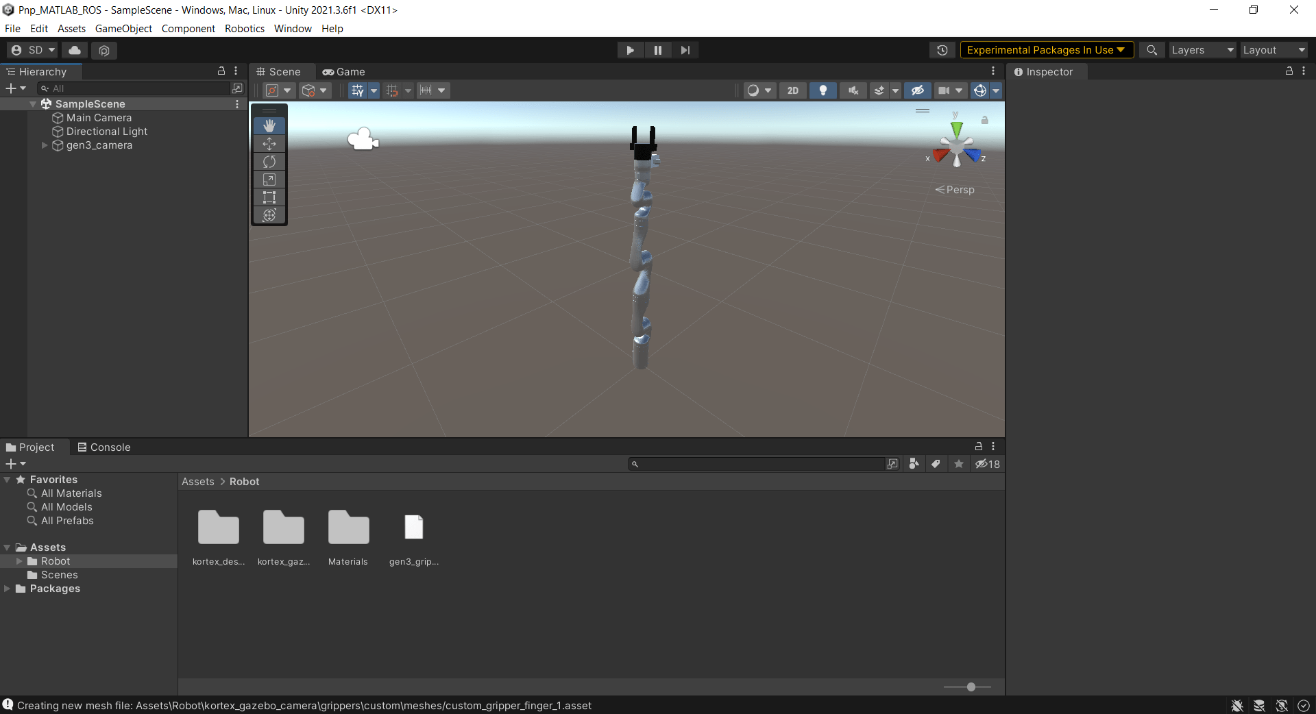
The Robot.zip file included with this example contains the URDF file of the Kinova Gen3 robot with a custom gripper attached to it. The file also contains the relevant mesh files for the robot model.
To import the URDF model into Unity:
Extract the contents of the
Robot.zipfile to theAssetsfolder in the Unity project directory.Right-click the URDF file in the Project pane and select Import Robot from Selected URDF file.
In the URDF Import Settings window, click Import URDF.


Zoom into the scene to view the imported Kinova Gen3 robot model.

Set Up Scene in Unity
To simulate a pick-and-place workflow in Unity, create an environment in Unity containing a floor, a table, and a box to be picked.
Add Floor
From the Unity menu, select GameObject > 3D Object > Plane. Unity Editor adds a plane to the scene and lists it in the Hierarchy pane.
In the Hierarchy pane, right-click the plane object and select Rename. Rename it as
Floor.In the Inspector pane, under Transform, set the X, Y, and Z values of Position to
0.

Add Table
From the Unity menu, select GameObject > 3D Object > Cube. Unity Editor adds a cube to the scene and lists it in the Hierarchy pane.
In the Hierarchy pane, right-click the cube object and select Rename. Rename it as
Table.In the Inspector pane, under Transform, set the Y and Z values of Position to
0.25and set Y value of Scale to0.5.

Add Box
From the Unity menu, select GameObject > 3D Object > Cube. Unity Editor adds a cube to the scene and lists it in the Hierarchy pane.
In the Hierarchy pane, right-click the cube object and select Rename. Rename it as
Box.In the Inspector pane, under Transform, set the Y value of Position to
0.525and Z value of Position to0.25.Set the X, Y, and Z values of Scale to
0.05.In the Inspector pane, under Mesh Renderer, change the Material property of the box to a non-default color for ease of visualization.
Click Add Component and search for
rigidbody.Select the RigidBody component to add it to the Inspector pane.
In the Inspector pane, under RigidBody, set the value of Mass to
0.01. If Use Gravity is not selected, select it.

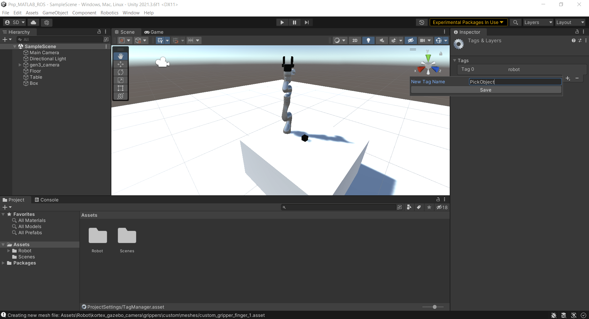
Add Tag to Box
In the Hierarchy pane, select Box.
In the Inspector pane, click the Tag dropdown and select Add Tag.
Click the + sign to create a tag. Name the tag
PickObject.In the Hierarchy pane, select Box.
In the Inspector pane, click the Tag dropdown and select PickObject.


You can repeat the steps in Add Box and Add Tag to Box to add more objects for the robot to pick.
Adjust Camera
In the Hierarchy pane, select Main Camera.
In the Inspector pane, under Transform, adjust the Position and Rotation properties.
Alternatively, you can manually adjust the camera position and orientation using the tool overlay in the Scene pane.
You can preview the point of view of the camera while adjusting it.

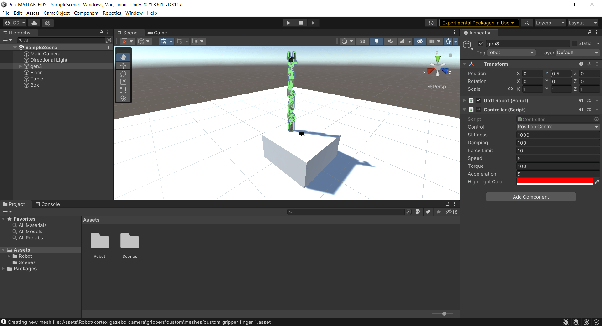
Configure Robot Model in Unity
To configure the robot model:
In the Hierarchy pane, select the robot object gen3_camera.
In the Inspector pane, under Transform, set the Y value of Position to
0.5, which positions the robot on the top of the table.Under Controller (Script), set Stiffness to
1000, Damping to100, and Force Limit to10.Rename the robot object to gen3, to match the robot name used in the
setCurrentRobotJConfigmethod of theexampleHelperCoordinatorPickPlaceROSUnityclass.
The setCurrentRobotJConfig method of the exampleHelperCoordinatorPickPlaceROSUnity class uses this code.
function configRespUnity = setCurrentRobotJConfig(obj,JConfig)
    disp("Sending robots to initial positions...")

    %For Unity
    configReqUnity = rosmessage(obj.ROSinfo.UnityConfigClient);
    configReqUnity.ModelName = "gen3";
    configReqUnity.JointPositions = JConfig;
    configRespUnity = call(obj.ROSinfo.UnityConfigClient,configReqUnity,"Timeout",3);
end

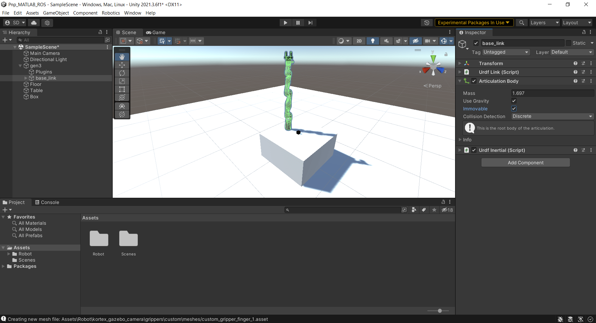
To configure the base link of the robot model:
In the Hierarchy pane, under the gen3 robot object, select base_link.
In the Inspector pane, under Articulation Body, select Immovable.
To add collision boxes to the gripper fingers:
In the Hierarchy pane, under the gen3 robot object, select gripper_finger1_finger_tip_link.
In the Inspector pane, click Add Component and search for
box collider.Select the Box Collider component to add it to the Inspector pane.
Adjust the values of the Center and Size properties of the collision box to ensure that it aligns with the gripper finger mesh.
Repeat the previous steps for gripper_finger2_finger_tip_link.


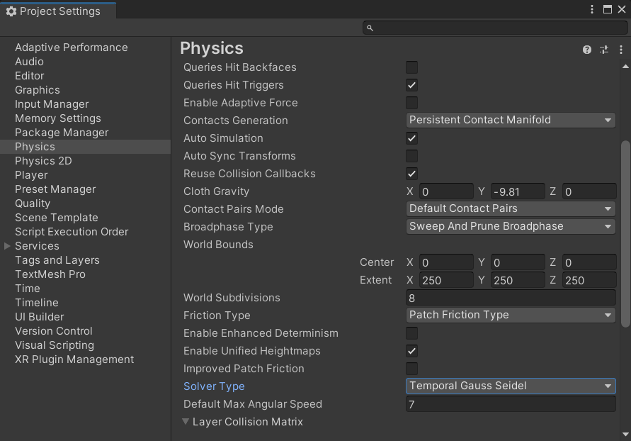
To set the physics solver type:
From the menu, select Edit > Project Settings to launch the Project Settings window.
In the left pane of the Project Settings window, select Physics.
In the Physics settings pane, set Solver Type to Temporal Gauss Seidel.
ROS Custom Services and Publisher
MATLAB needs to communicate with Unity in order to transmit and receive information regarding the robot model. The execution of the pick-and-place workflow requires channels of communication between MATLAB and Unity. To establish communication for these channels, use custom services and a publisher.
This example includes the ROS custom service definition (.srv) files. You can find these files inside the unity_robotics_demo_msgs folder. The Generate Unity Scripts for Custom Services section shows how to generate ROS messages from the custom service definition files in Unity. The Generate Custom ROS Messages in MATLAB section shows how to generate ROS messages from the custom service definition files in MATLAB.
SetModelConfiguration.srv— Sends the robot joint configuration from MATLAB to Unity.FollowTrajectory.srv— Sends the robot joint-space trajectory from MATLAB to Unity.ObjectPosition.srv— Receives the position of the box to be picked from the Unity scene in MATLAB.MoveGripperCommand.srv— Sends the command to open or close the gripper fingers from MATLAB.
The PNPScripts.zip file included with this example contains C# (.cs) scripts you can use to establish communication between Unity and MATLAB. The Add ROS Service Scripts in Unity section shows how to add the Unity ROS service scripts to the scene. For more examples of implementing the Unity ROS service, see these Unity Scripts in the Unity Robotics Hub GitHub repository.

SetModelConfiguration.cs— Receives the robot joint configuration from MATLAB in Unity. Unity then assigns these joint configuration values to the corresponding joints of the robot model. The script also clears the Use Gravity option in all the links of the robot during simulation.FollowTrajectory.cs— Moves the robot model along a set of joint configurations provided by the trajectory from MATLAB.ObjectPosition.cs— Sends the position of the box to be picked from the Unity scene to MATLAB.MoveGripper.cs— Opens or closes the gripper fingers attached to the robot arm in Unity.JointStatePublisher.cs— Publishes the current joint configuration from Unity to the ROS network in MATLAB. For more information on publishing messages from Unity, see ROS–Unity Communication.
Generate Unity Scripts for Custom Services
You must build the ROS custom service definition files into C# scripts for use in Unity programming. The ROS TCP Connector package provides a tool you can use to build messages and services.
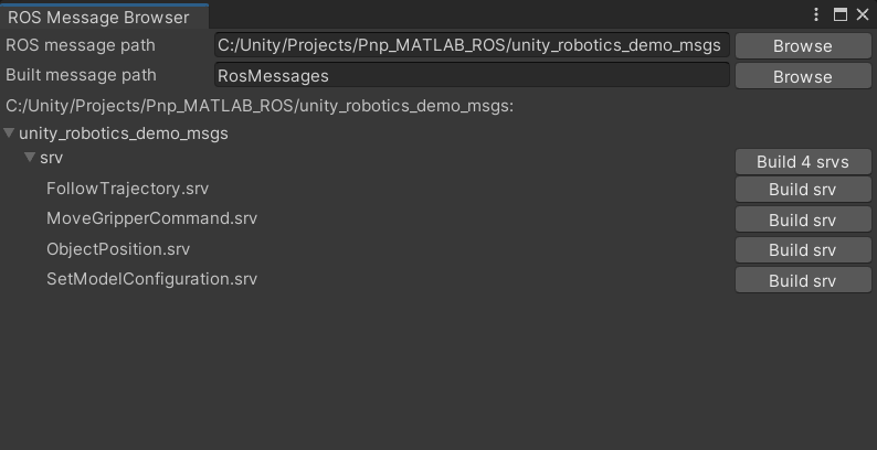
To build the custom services:
Copy the
unity_robotics_demo_msgsfolder, which contains the ROS custom service definition files, to the Unity project folder. For more information on the service definition files in theunity_robotics_demo_msgsfolder, see the ROS Custom Services and Publisher section.From the Unity menu bar, select Robotics > Generate ROS Messages, to launch the tool for building custom services.
In the ROS Message Browser window, browse to the
unity_robotics_demo_msgsfolder inside the Unity project folder.Click Build 4 srvs.

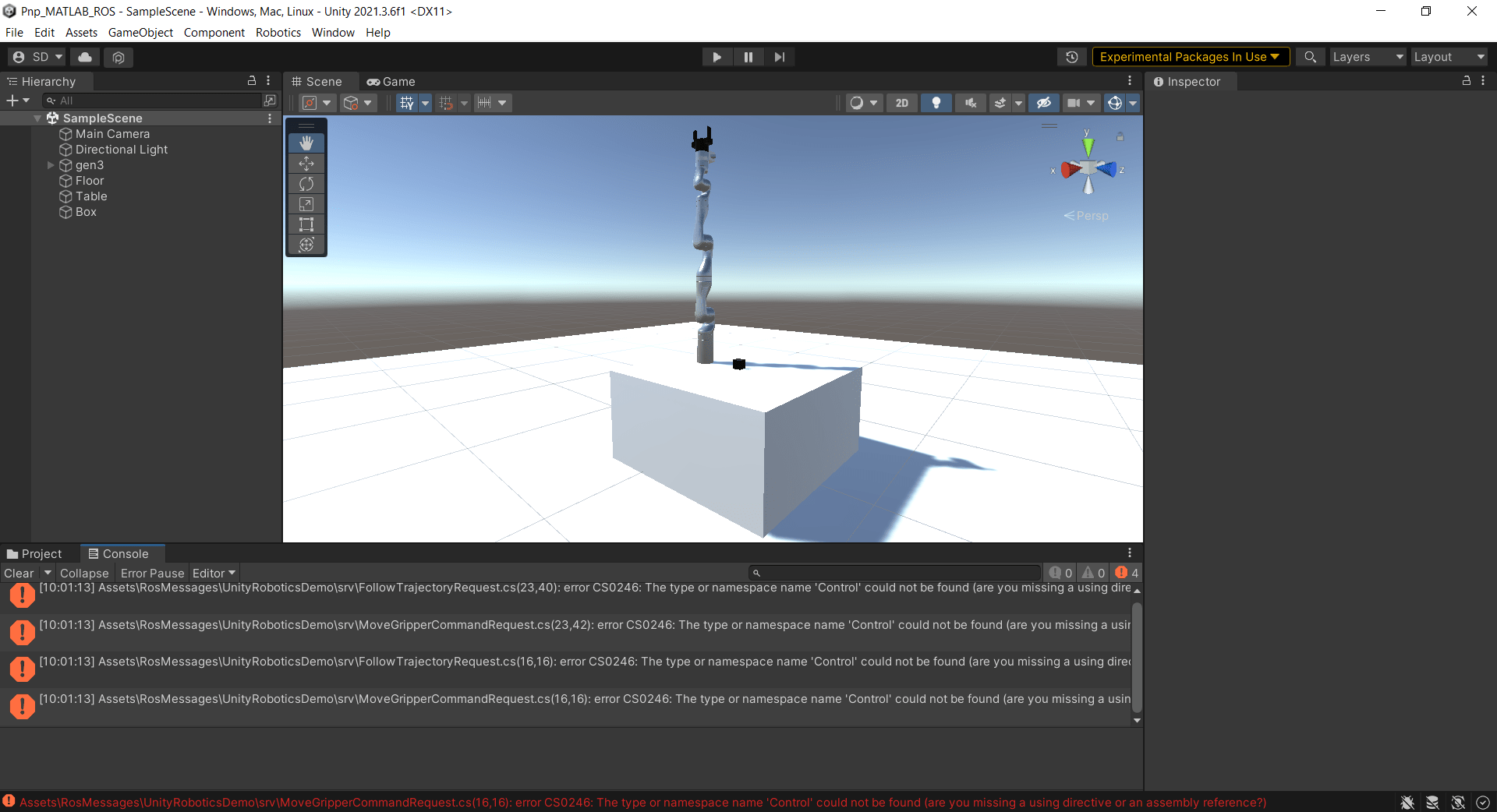
Unity generates C# service scripts from the ROS custom service definition files.
Unity also returns errors regarding the missing control_msgs messages.

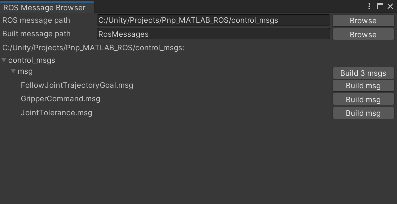
To build the required control_msgs messages:
Extract the Control_Msgs
.zipfile inside the Unity project folder. For more information on ROS control messages, see control_msgs GitHub® repository.From the Unity menu bar, select Robotics > Generate ROS Messages, to launch the tool for building these messages.
In the ROS Message Browser window, browse to the
control_msgsfolder inside the Unity project folder.Build only these messages, named in the errors returned by Unity: FollowJointTrajectoryGoal.msg, GripperCommand.msg, and JointTolerance.msg.
Click Build 3 msgs.

Unity generates C# message scripts from the control_msgs message definition files, which resolves the errors.
Add ROS Service Scripts in Unity
To add the Unity ROS service scripts to the scene:
Extract the
PNPScripts.zipfile to theAssetsfolder in the Unity project directory. For more information on the service scripts in thePNPScripts.zipfile, see the ROS Custom Services and Publisher section.From the Unity menu bar, select GameObject > Create Empty. Unity adds an empty GameObject to the scene and lists it in the Hierarchy pane.
Rename the empty GameObject to PNPScriptsObject.
In the Project pane, select all of the C# script files in the
PNPScriptsfolder.Drag the files to PNPScriptsObject in the Hierarchy pane.

The scripts are added as components of PNPScriptsObject. In the Hierarchy pane of PNPScriptsObject, set the Gen 3 property of the Follow Trajectory, Joint State Publisher, Move Gripper, and Set Model Configuration components to the gen3 robot object.
Create Pick-and-Place Workflow in MATLAB
This example uses a Stateflow chart to schedule the tasks of the pick-and-place workflow. Open the chart to examine the contents and follow the state transitions during chart execution.
edit exampleHelperFlowChartPickPlaceROSUnity.sfx
The chart dictates how the manipulator interacts with the objects, or parts. It consists of basic initialization steps, followed by two main sections:
Identify parts and determine where to place them.
Execute the pick-and-place workflow.
For a high-level description of the pick-and-place steps, see Pick-and-Place Workflow Using Stateflow for MATLAB.
Opening and Closing Gripper
The exampleCommandActivateGripperROSUnity command function sends a service request to open and close the gripper implemented in Unity.
Moving Manipulator to Specified Pose
Use the exampleCommandMoveToTaskConfigROSUnity command function to move the manipulator to specified poses. After generating a joint trajectory for the robot to follow, the exampleCommandMoveToTaskConfigROSUnity function samples the trajectory at the desired sample rate, then packages it into joint-trajectory ROS messages, and sends a service request to Unity.
Trajectory Planning
Use trapveltraj and transformtraj functions to generate simple task-space trajectories from an initial to a desired task configuration. For more details on planning and executing trajectories, see Plan and Execute Task- and Joint-Space Trajectories Using Kinova Gen3 Manipulator.
Generate Custom ROS Messages in MATLAB
You must generate ROS custom messages in MATLAB from the custom service definition files inside the unity_robotics_demo_msgs folder. For more information on these service definition files, see the ROS Custom Services and Publisher section.
Use the rosgenmsg (ROS Toolbox) function to generate the custom messages, and follow the instructions in the dialog box to add the messages to the MATLAB path.
answer = questdlg("Are the Custom ROS messages generated for MATLAB?", ...
    "Custom ROS messages for MATLAB","Yes","No", "No");
switch answer
    case "Yes"
        % Continue with pick and place
    case "No"
        % Run rosgenmsg to build custom ROS messages for MATLAB
        rosgenmsg
end

answer = questdlg("Are the Custom ROS messages added to MATLAB path?", ...
    "ROS messages","Yes","Add path...", "Add path from current directory", "Yes");

switch answer
    case "Yes"
        % Continue with pick and place
    case "Add path..."
        % Add the custom ROS messages to the MATLAB path
        customROSMsgPath = uigetdir("", "Select the install\m folder created by rosgenmsg");
        addpath(customROSMsgPath)
        savepath
        clear classes
        rehash toolboxcache
    case "Add path from current directory"
        customROSMsgPath = uigetdir(fullfile(pwd, "matlab_msg_gen_ros1"), "Select the install\m folder created by rosgenmsg");
        addpath(customROSMsgPath)
        savepath
        clear classes
        rehash toolboxcache
end
Integrate MATLAB with Unity for ROS Communication
Start the ROS master from MATLAB. Alternatively, you can connect Unity and MATLAB to a ROS master running elsewhere. Start the ROS TCP endpoint node in MATLAB to facilitate the communication between Unity and ROS for sending and receiving messages.
Configure Unity to connect with the ROS master by specifying the IP address within Unity's ROS settings. You must verify that Unity's simulation environment is correctly connected to MATLAB, with instructions on how to check for errors in Unity and confirm the connection status through MATLAB using ROS topics.
Check Set Up and Connect to Unity Game Engine (ROS Toolbox) topic for detailed steps.
Start Pick-and-Place Task
Load Robot Model in MATLAB
This simulation uses a Kinova Gen3 manipulator with a Robotiq gripper attached. Load the robot model from a .mat file as a rigidBodyTree object.
load("exampleHelperKINOVAGen3GripperROSUnity.mat");Initialize Pick-and-Place Coordinator
Set the initial robot configuration. Initialize the coordinator, which handles the robot control, by specifying the robot model, initial configuration, and end-effector name.
initialRobotJConfig =  [3.5797 -0.6562 -1.2507 -0.7008 0.7303 -2.0500 -1.9053];
endEffectorFrame = "gripper";
coordinator = exampleHelperCoordinatorPickPlaceROSUnity(robot,initialRobotJConfig,endEffectorFrame);
In Unity, verify that the robot model has moved to the position specified by initialRobotJConfig.
Specify the home configuration and two poses for placing objects.
coordinator.HomeRobotTaskConfig = getTransform(robot,initialRobotJConfig,endEffectorFrame);
coordinator.PlacingPose{1} = trvec2tform([0.2 0.55 0.26])*axang2tform([0 0 1 pi/2])*axang2tform([0 1 0 pi]);
coordinator.PlacingPose{2} = trvec2tform([0.2 -0.55 0.26])*axang2tform([0 0 1 pi/2])*axang2tform([0 1 0 pi]);
Run and Visualize Simulation
Connect the coordinator to the Stateflow chart. Once started, the Stateflow chart is responsible for continuously going through the states of detecting objects, picking them up, and placing them in the correct staging area.
coordinator.FlowChart = exampleHelperFlowChartPickPlaceROSUnity("coordinator",coordinator);Create a dialog box for starting the pick-and-place task execution. To begin the simulation, click Yes in the dialog box.
answer = questdlg("Do you want to start the pick-and-place job now?", ...
    "Start job","Yes","No", "No");

switch answer
    case "Yes"
        % Trigger event to start Pick and Place in the Stateflow Chart
        coordinator.FlowChart.startPickPlace;
    case "No"
        coordinator.FlowChart.endPickPlace;
        delete(coordinator.FlowChart)
        delete(coordinator)
end
Observe the robot model in Unity, and check that it performs the pick-and-place actions.


End Pick-and-Place Task
The Stateflow chart stops automatically after four failed attempts to detect new objects. To stop the pick-and-place task prematurely, uncomment and execute these lines of code or select the command window and press Ctrl+C.
% coordinator.FlowChart.endPickPlace;
% delete(coordinator.FlowChart)
% delete(coordinator)
Visualize Pick-and-Place Action in Unity
The Unity scene shows the robot in the working area as it moves the objects to the desired location. The robot continues working until all objects have been placed. When the detection step does not find any more objects four times, the Stateflow chart ends.
if strcmp(answer,"Yes")
    while  coordinator.NumDetectionRuns <  4
        % Wait for no objects to be detected.
    end
end
Kill the ROS TCP endpoint node and shut down the ROS network.
helperKillTCPEndpointNode;
rosshutdown;