Main Content

Transmitter

Transmitter object belonging to satellite scenario

Since R2021a

    Description

    Transmitter defines a transmitter object belonging to a satellite scenario.

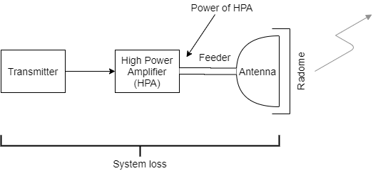
    For an illustration of the signal power of a high power amplifier (HPA) and the system loss encountered at a transmitter, see Algorithms.

    Creation

    You can create Transmitter objects using the transmitter function of satellite, platform, groundStation, or gimbal.

    Properties

    expand all

    You can set this property only when calling the transmitter function. After you call the transmitter function, this property is read-only.

    Transmitter name, specified as a name-value argument consisting of 'Name' and a string scalar, string vector, character vector, or a cell array of character vectors.

    • If you are adding only one transmitter, specify Name as a string scalar or a character vector.

    • If you are adding multiple transmitters, specify Name as a string scalar, character vector, string vector, or a cell array of character vectors. All transmitters that you add as a string scalar or a character vector are assigned the same specified name. The number of elements in the string vector or cell array of character vectors must equal the number of transmitters that you are adding. Each transmitter is assigned the corresponding name from the vector or cell array.

    In the default value, idx is the ID assigned by the satellite scenario.

    Data Types: char | string

    This property is set internally by the simulator and is read-only.

    Transmitter ID assigned by the simulator, specified as a positive scalar.

    Mounting location with respect to the parent object in meters, specified as a three-element vector or a matrix. The position vector is specified in the body frame of the input parent.

    • If you are adding one transmitter, MountingLocation is a three-element vector. The elements specify the x, y, and z components of the Cartesian coordinates in the body frame of transmitter.

    • If you are adding multiple transmitters, MountingLocation can be a three-element vector or a matrix. When specified as a vector, the same set of mounting locations are assigned to all specified transmitters. When specified as a matrix, MountingLocation must contain three rows and the same number of columns as the transmitters. The columns correspond to the mounting location of each specified transmitter and the rows correspond to the mounting location coordinates in the parent body frame.

    When the AutoSimulate property of the satellite scenario is false, you can modify the MountingLocation property only when SimulationStatus is NotStarted. You can use the restart function to reset SimulationStatus to NotStarted, but doing so erases the simulation data.

    Data Types: double

    Mounting orientation with respect to parent object in degrees, specified as a three-element row vector of positive numbers. The elements of the vector correspond to yaw, pitch, and roll, in that order. Yaw, pitch, and roll are positive rotations about the z-axis, intermediate y-axis, and intermediate x-axis of the parent.

    • If you are adding one transmitter, the MountingAngles property is a three-element vector.

    • If you are adding multiple transmitters the MountingAngles property can be a three-element vector or a matrix. When specified as a vector, the same set of mounting angles are assigned to all specified transmitters. When specified as a matrix, MountingAngles must contain three rows and the same number of columns as the transmitters. The columns correspond to the mounting angles of each specified transmitter and the rows correspond to the yaw, pitch, and roll angles in the parent body frame.

    When the AutoSimulate property of the satellite scenario is false, you can modify the MountingAngles property only when SimulationStatus is NotStarted. You can use the restart function to reset SimulationStatus to NotStarted, but doing so erases the simulation data.

    Example: [0; 30; 60]

    Data Types: double

    Antenna object associated with the transmitter, specified as either a scalar or a vector. This object can be the default gaussianAntenna object, or one from the Antenna Toolbox or Phased Array System Toolbox. The default Gaussian antenna has a dish diameter of 1 meter and an aperture efficiency of 0.65.

    Antenna can be specified in transmitter as a name-value argument consisting of 'Antenna' and a scalar, antenna or phased array objects.

    • If you are adding only one transmitter, Antenna must be a scalar.

    • If you are adding multiple transmitters, Antenna is a vector. The same antenna is assigned to all transmitters.

    Total system loss in the transmitter in dB, specified as a scalar or a vector.

    System loss can be specified in transmitter as a name-value argument consisting of 'SystemLoss' and a scalar, or vector.

    • If you are adding only one transmitter, specify SystemLoss as a scalar.

    • If you are adding multiple transmitters are added, specify SystemLoss as a scalar or a vector. When SystemLoss is a scalar, the same SystemLoss is assigned to all transmitters. When SystemLoss is a vector, its length must equal the number of transmitter and each element of SystemLoss is assigned to the corresponding transmitter in the parent.

    When the AutoSimulate property of the satellite scenario is false, you can modify the SystemLoss value while SimulationStatus is NotStarted or InProgress.

    Transmitter frequency in Hz, specified as a name-value argument consisting of 'Frequency' and a scalar or a vector.

    • If you are adding only one transmitter, the Frequency must be a scalar.

    • If you are adding multiple transmitters are added, the frequency value can be a scalar or a vector. All transmitters added as a scalar are assigned the same specified Frequency. The length of the vector must equal the number of transmitters added and each element of Frequency is assigned to the corresponding transmitter in the parent.

    When the AutoSimulate property of the satellite scenario is false, you can modify the Frequency value while SimulationStatus is NotStarted or InProgress.

    Bit rate of the transmitter in Mbps, specified as a name-value pair consisting of 'BitRate' and a scalar or a vector.

    • If you are adding only one transmitter, the bit rate value must be a scalar.

    • If you are adding multiple transmitters, the bit rate value can be a scalar or a vector. All transmitters added as a scalar are assigned the same specified BitRate. The length of the vector must equal the number of transmitters added and each element of BitRate is assigned to the corresponding transmitter in the parent.

    When the AutoSimulate property of the satellite scenario is false, you can modify the BitRate value while SimulationStatus is NotStarted or InProgress.

    Signal power at the output of a high power amplifier in dbW, specified as a name-value pair consisting of 'Power' and a scalar or a vector.

    • If you are adding only one transmitter, the power value must be a scalar.

    • If you are adding multiple transmitters, the power value can be a scalar or a vector. All transmitters added as a scalar are assigned the same specified Power. The length of the vector must equal the number of transmitters added and each element of Power is assigned to the corresponding transmitter in the parent.

    When the AutoSimulate property of the satellite scenario is false, you can modify the Power value while SimulationStatus is NotStarted or InProgress.

    You can set this property only when calling coordinateAxes. After you call coordinateAxes, this property is read-only.

    Coordinate axes triad graphic object, specified as CoordinateAxes object.

    This property is read-only.

    Link analysis objects, specified as a row vector Link objects.

    Object Functions

    aerCalculate azimuth angle, elevation angle, and range of another satellite or ground station in NED frame
    gaussianAntennaAdd Gaussian antennas
    linkAdd link analysis objects to transmitter
    patternPlot 3-D radiation pattern of antenna
    pointAtPoint transmitter or receiver at target
    pointAtPoint satellite at target
    coordinateAxesVisualize coordinate axes triad of satellite scenario assets
    dopplershiftCalculate Doppler shift at target asset in satellite scenario

    Examples

    collapse all

    Create a satellite scenario object.

    startTime = datetime(2020,11,25,0,0,0);
    stopTime = startTime + days(1);
    sampleTime = 60;                                     % seconds
    sc = satelliteScenario(startTime,stopTime,sampleTime)
    sc = 
      satelliteScenario with properties:
    
             StartTime: 25-Nov-2020
              StopTime: 26-Nov-2020
            SampleTime: 60
          AutoSimulate: 1
            Satellites: [1×0 matlabshared.satellitescenario.Satellite]
        GroundStations: [1×0 matlabshared.satellitescenario.GroundStation]
               Viewers: [0×0 matlabshared.satellitescenario.Viewer]
              AutoShow: 1


    Add a satellite to the scenario.

    semiMajorAxis = 10000000;                                                                  % meters
    eccentricity = 0;
    inclination = 60;                                                                          % degrees
    rightAscensionOfAscendingNode = 0;                                                         % degrees
    argumentOfPeriapsis = 0;                                                                   % degrees
    trueAnomaly = 0;                                                                           % degrees
    sat = satellite(sc,semiMajorAxis,eccentricity,inclination,rightAscensionOfAscendingNode, ...
            argumentOfPeriapsis,trueAnomaly,Name="Satellite");

    Add gimbals to the satellite. These gimbals enable the satellite receiver antenna to steer to the first ground station, and its transmitter antenna to steer to the second ground station.

    gimbalrxSat = gimbal(sat);
    gimbaltxSat = gimbal(sat);

    Add a receiver to the first gimbal of the satellite.

    gainToNoiseTemperatureRatio = 5;                                                        % dB/K
    systemLoss = 3;                                                                         % dB
    rxSat = receiver(gimbalrxSat,Name="Satellite Receiver",GainToNoiseTemperatureRatio= ...
        gainToNoiseTemperatureRatio,SystemLoss=systemLoss)
    rxSat = 
      Receiver with properties:
    
                               Name:  Satellite Receiver
                                 ID:  4
                   MountingLocation:  [0; 0; 0] meters
                     MountingAngles:  [0; 0; 0] degrees
                            Antenna:  [1x1 satcom.satellitescenario.GaussianAntenna]
                         SystemLoss:  3 decibels
                    PreReceiverLoss:  3 decibels
        GainToNoiseTemperatureRatio:  5 decibels/Kelvin
                       RequiredEbNo:  10 decibels


    Add a transmitter to the second gimbal of the satellite.

    frequency = 27e9;                                                                     % Hz
    power = 20;                                                                           % dBW
    bitRate = 20;                                                                         % Mbps
    systemLoss = 3;                                                                       % dB
    txSat = transmitter(gimbaltxSat,Name="Satellite Transmitter",Frequency=frequency, ...
        power=power,BitRate=bitRate,SystemLoss=systemLoss)
    txSat = 
      Transmitter with properties:
    
                    Name:  Satellite Transmitter
                      ID:  5
        MountingLocation:  [0; 0; 0] meters
          MountingAngles:  [0; 0; 0] degrees
                 Antenna:  [1x1 satcom.satellitescenario.GaussianAntenna]
              SystemLoss:  3 decibels
               Frequency:  2.7e+10 Hertz
                 BitRate:  20 Mbps
                   Power:  20 decibel-watts
                   Links:  [1x0 satcom.satellitescenario.Link]


    Specify the antenna specifications of the repeater.

    dishDiameter = 0.5;                                                                    % meters
    apertureEfficiency = 0.5;
    gaussianAntenna(txSat,DishDiameter=dishDiameter,ApertureEfficiency=apertureEfficiency);
    gaussianAntenna(rxSat,DishDiameter=dishDiameter,ApertureEfficiency=apertureEfficiency);

    Add two ground stations to the scenario.

    gs1 = groundStation(sc,Name="Ground Station 1");
    latitude = 52.2294963;                                              % degrees
    longitude = 0.1487094;                                              % degrees
    gs2 = groundStation(sc,latitude,longitude,Name="Ground Station 2");

    Point gimbals of the satellite towards the two ground stations for the simulation duration.

    pointAt(gimbaltxSat,gs2);
    pointAt(gimbalrxSat,gs1);

    Add gimbals to the ground stations. These gimbals enable the ground station antennas to steer towards the satellite.

    gimbalgs1 = gimbal(gs1);
    gimbalgs2 = gimbal(gs2);

    Add a transmitter to ground station gs1.

    frequency = 30e9;                                                                          % Hz
    power = 40;                                                                                % dBW
    bitRate = 20;                                                                              % Mbps
    txGs1 = transmitter(gimbalgs1,Name="Ground Station 1 Transmitter",Frequency=frequency, ...
            Power=power,BitRate=bitRate);

    Add a receiver to ground station gs2.

    requiredEbNo = 14;                                                                     % dB
    rxGs2 = receiver(gimbalgs2,Name="Ground Station 2 Receiver",RequiredEbNo=requiredEbNo);

    Define the antenna specifications of the ground stations.

    dishDiameter = 5;                                % meters
    gaussianAntenna(txGs1,DishDiameter=dishDiameter);
    gaussianAntenna(rxGs2,DishDiameter=dishDiameter);

    Point gimbals of the ground stations towards the satellite for the simulation duration.

    pointAt(gimbalgs1,sat);
    pointAt(gimbalgs2,sat);

    Add link analysis to transmitter txGs1.

    lnk = link(txGs1,rxSat,txSat,rxGs2)
    lnk = 
      Link with properties:
    
        Sequence:  [10 4 5 11]
        LineWidth:  2
        LineColor:  [0.3922 0.8314 0.0745]


    Determine the times when ground station gs1 can send data to ground station gs2 via the satellite.

    linkIntervals(lnk)
    ans=4×8 table
                    Source                          Target               IntervalNumber         StartTime                EndTime           Duration    StartOrbit    EndOrbit
        ______________________________    ___________________________    ______________    ____________________    ____________________    ________    __________    ________
    
        "Ground Station 1 Transmitter"    "Ground Station 2 Receiver"          1           25-Nov-2020 00:21:00    25-Nov-2020 00:40:00      1140         NaN          NaN   
        "Ground Station 1 Transmitter"    "Ground Station 2 Receiver"          2           25-Nov-2020 03:19:00    25-Nov-2020 03:36:00      1020         NaN          NaN   
        "Ground Station 1 Transmitter"    "Ground Station 2 Receiver"          3           25-Nov-2020 06:15:00    25-Nov-2020 06:36:00      1260         NaN          NaN   
        "Ground Station 1 Transmitter"    "Ground Station 2 Receiver"          4           25-Nov-2020 22:20:00    25-Nov-2020 22:38:00      1080         NaN          NaN   


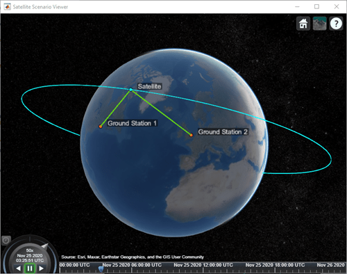
    Visualize the link by using the Satellite Scenario Viewer.

    play(sc);

    Algorithms

    This diagram shows the signal power of a HPA and the system loss experienced at the transmitting end.

    At the transmitting side, system loss spans from the transmitter to the transmitting antenna, via the high power amplifier and the feeder cable.

    Version History

    Introduced in R2021a