Torque Converter
R2026bTorque converter coupling between two drive shafts
Torque Converter block

To add a block to a model, double-click the canvas and start typing the block name. Then, select the block from the list.
Libraries:
Simscape /
Driveline /
Couplings & Drives
Description
The Torque Converter block represents an automotive torque converter that comprises an impeller, a turbine, and a stator. The impeller and the turbine make up the fluid coupling, and the stator increases torque by redirecting the flow returning to the impeller. As the shaft turns the impeller, centrifugal force flings the fluid outward toward the turbine blades, which causes the turbine to spin as the fluid proceeds to the center and out toward the stator. Use the block to connect an engine to an automatic transmission. Connect port I to the engine and port T to the transmission.

The block operates in drive mode when power flows from port I to port T. The block operates in coast mode when power flows in reverse. You can simulate the coast mode transition continuously or by using mode charts. The block uses the capacity factor for the torque converter to calculate the torque from the angular speed.
Use modal coast mode modeling
When you set Coast mode modeling to Two
mode, the block uses separate modes for coasting and driving. The block
computes the torque from the angular speed such that
where K* is the Drive mode capacity factor vector parameter and ω is the angular speed for either port I or port T. The capacity factor is a function of the speed ratio. When in drive mode, the block defines the speed ratio as
where ωT and ωI represent the speeds at ports T and I, respectively. When in coast mode, the block defines the speed ratio as
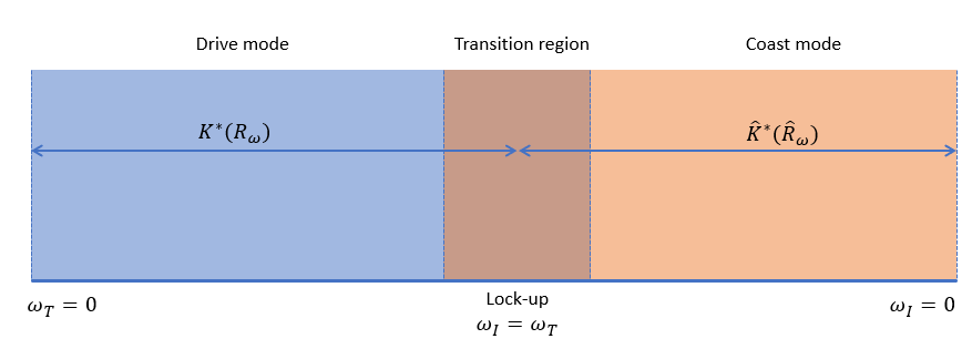
Because the block uses separate speed ratio definitions, it also uses a separate capacity factor for the coast mode, , which is the Coast mode capacity factor vector parameter. The Mode transition parameter determines the speed at which the block changes modes. The figure illustrates the two modes.
You can optionally include dampers,inertias, and lock-up clutch behavior.
When you select Enable dampers and inertias, the block uses a subcomponent implementation of Damper and Inertia blocks for both the impeller and turbine sides of the torque converter. The figure illustrates the implementation.
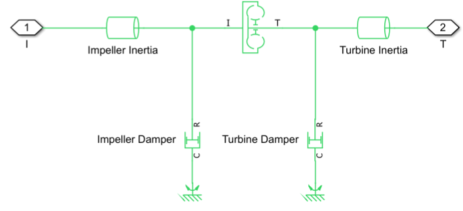
You can use the parameters in the Dampers and Inertias section to modify the damper and inertia for the two sides of the torque converter.
When you select Enable lock-up clutch, the block uses a subcomponent implementation of the Disc Friction Clutch block to simulate lock-up clutch behavior. The figure illustrates the implementation.
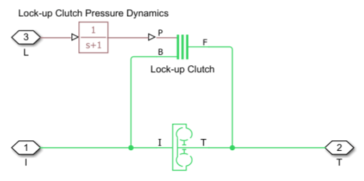
The block introduces a first-order delay to the lock-up clutch pressure port. This delay represents the clutch pressure dynamics. The block uses the input pressure, Pin, to find the clutch torque, such that
where,
Pmin is the minimum pressure at which the clutch engages, specified by the Engagement threshold pressure parameter.
A is the effective piston engagement area, specified by the Engagement piston area parameter.
R is the effective torque radius, specified by the Effective torque radius parameter.
You can use port L to provide Pin as a physical signal. To parameterize the clutch and pressure dynamics, use the parameters associated with the subcomponent implementation under the Lock-up Clutch and Lock-up Clutch Pressure Dynamics sections in the block dialog box.
Use Continuous Coast Mode Modeling
When you set Coast mode modeling to
Continuous, the block smoothly transitions between drive and
coast mode. You can also add dynamics. The block simulation is less accurate when operating
near the transition region.
The block defines the speed ratio as and the torque ratio as . The Capacity factor parameterization parameter controls how the block defines the capacity factor. When you select:
Ratio of speed to square root of impeller torque, the block uses .Ratio of impeller torque to square of speed, the block uses .
By default, the block constrains , the torque at port T, and , the torque at port I, to one another for a given time step. You can optionally include the effect of torque transmission time lag that is caused by internal fluid flow and compressibility. The block introduces the lag and finds the steady state torque at port I such that
The instantaneous function of the capacity factor K determines the steady-state value of τI.
To improve fidelity, you can include lag due to the transmission in your simulation.
When you set Model transmission lag to Specify time
constant and initial value, the block adds a constant time delay to the
torque transfer.
When you set Coast mode modeling to
Continuous:
The impeller shaft must always rotate in a positive direction. Simulation is not valid for < 0.
If you drive the Torque Converter block by using a torque source, such as the Generic Engine block, you must include an inertia in the source to represent the engine, shaft inertia, or other source components. To ensure that the impeller starts by rotating in a positive direction, set the initial speed for this inertia to a positive value.
Examples
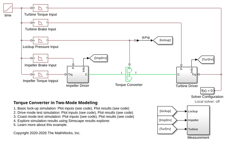
Torque Converter in Two-Mode Modeling
Basic operations of a torque converter including lock-up clutch mechanism. You can select three different simulation cases - Basic Lock-up, Drive Mode Test, and Coast Mode Test.
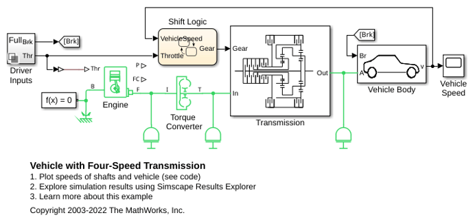
Vehicle with Four-Speed Transmission
A complete vehicle with Simscape™ Driveline™ components, including the engine, drivetrain, four-speed transmission, tires, and longitudinal vehicle dynamics. The transmission controller is implemented as a state machine in Stateflow®, selecting the gear based on throttle and vehicle speed.
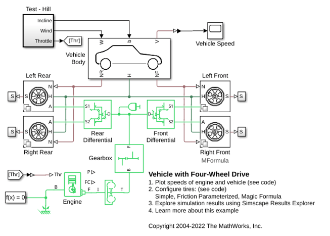
Vehicle with Four-Wheel Drive
A four-wheel drive vehicle starting from rest and ascending a 15 degree incline. Initially the vehicle rolls backward until the engine develops sufficient torque to counter the slope. The tire compliance dynamics can be seen as the vehicle starts to accelerate. The model variant chosen for all of the tires can be set to the Simple, Friction Parameterized, or Magic Formula tire model using the hyperlinks in the model.
Ports
Input
Conserving
Parameters
References
[1] Society of Automotive Engineers. "Hydrodynamic Drive Test Code (Surface Vehicle Recommended Practice)." SAE J643. (December 2018) https://doi.org/10.4271/J643_201812

