Network Coupler (Voltage-Current)
Libraries:
Simscape /
Utilities /
Network Couplers
Description
The Network Coupler (Voltage-Current) block provides a starting point for you to split a Simscape™ network into two coupled networks at an electrical connection. Use this block when Network 1 (as described in Naming Conventions) has series-connected inductors or current sources, but Network 2 does not.
This block changes the behavior of the system because it adds a first-order lag to break the algebraic loop.
Port 1 interface of the Network Coupler (Current-Voltage) block is implemented as a voltage source. Therefore, you cannot connect this port to a voltage loop, such as a set of series-connected voltage sources and capacitors, because this would cause an Index-2 topology (for more information, see Avoiding Numerical Simulation Issues). Port 2 interface is implemented as a current source. Therefore, you cannot connect this port to a series-connected inductor or current source because this would also cause an Index-2 topology.
To facilitate working with models that contain arrays of electrical nodes or three-phase connection, the Port 1 Interface and Port 2 Interface subsystems contain custom blocks, such as Controlled Voltage Source or Current Sensor. These custom blocks are based on the equivalent Foundation library blocks but are modified to support vectorized and three-phase electrical nodes. The source files for these custom blocks are located in the following namespace:
matlabroot/toolbox/physmod/simscape/library/m/+foundation/+internal/+couplers/+electrical
where matlabroot is the MATLAB® root directory on your machine, as returned by entering
matlabroot
at the MATLAB command prompt. The namespace contains source files for voltage and current sources and sensors, as well as a resistor and an electrical reference with array and three-phase support. You can use these blocks to customize your network coupler configuration.
Working with the Block on the Model Canvas
When you add the block to your model and double-click it, the Network Coupler (Voltage-Current) subsystem opens.
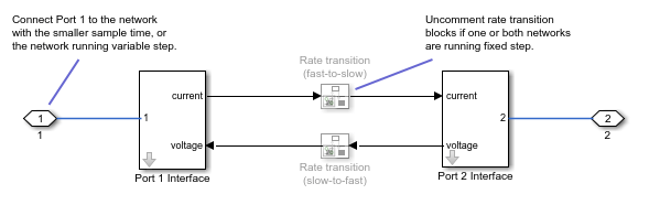
The Port 1 Interface block contains the dynamics that break the algebraic loop. Double-click this block to set all of the Network Coupler (Voltage-Current) subsystem parameters and view the derived values.
The rate transition blocks are, by default, commented through. Uncomment them if at least one of the coupled networks is running fixed step.
Using the Derived Values to Estimate Block Parameters
On the Analysis tab of the Port 1 Interface block dialog box, the Derived values section contains the Calculated fastest trackable time constant (s) value, based on the impact of the coupler lag. If both networks are variable-step, then you specify the filter time constant directly, as a block parameter. If at least one of the networks is fixed-step, the block calculates the time constant automatically based on the sample times that you specify, and the Derived values section displays the Calculated filter time constant (s) value.
The Update button lets you recalculate the derived values after you change the parameters of the connected networks.
Examples
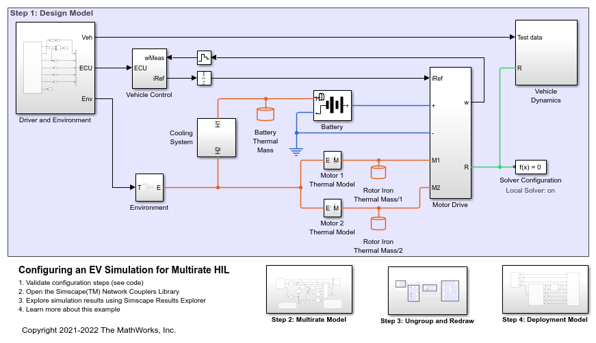
Configuring an EV Simulation for Multirate HIL
An electric vehicle model suitable for multirate Hardware-In-the-Loop (HIL) deployment. The example uses the Simscape™ Network Couplers Library to split the model into separate Simulink® subsystems that can be deployed at different sample rates. This allows you to run parts of the system (for example thermal components) with a slower sample time thereby reducing overall computational cost.