Merge Signals
R2026bThis example shows how to merge multiple input signals that update at different times into a single output signal. In Simulink®, you can use the Merge block to combine such signals.
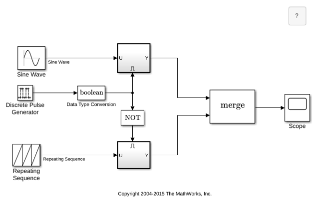
In the mergedemo model, a Merge block combines two signals generated using enabled subsystems into a single output. At any time, the value of the output signal equals the most recently computed output of its driving Enabled Subsystem block.
Open the model.
Model Behavior
In this model, a Pulse Generator block generates a pulse signal that toggles between zero and one every five seconds, controlling the subsystem execution. The outputs of the two enabled subsystems are used as inputs to the Merge block. The Merge block Initial output parameter is set to empty ([]) because the block sets its initial output to the initial value of one of its driving input signals. In this example, the initial output of the Merge block is the initial output of the top subsystem that executes when the simulation starts.
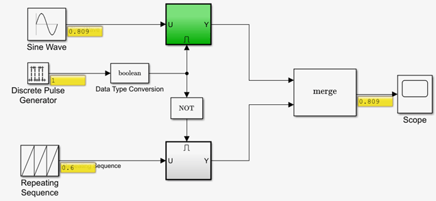
When the pulse signal is one, the top subsystem executes. The Merge block outputs the signal that the top subsystem generates.
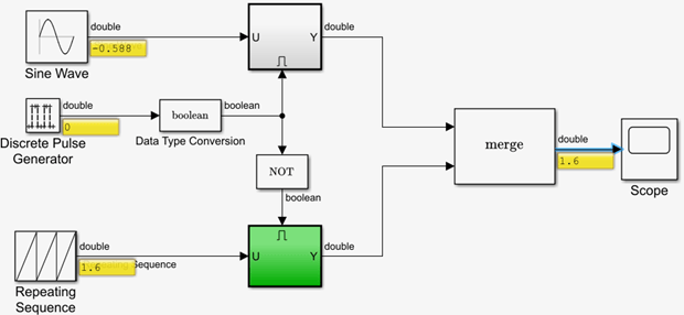
When the pulse signal is zero, the bottom subsystem executes. To enable the bottom subsystem when the pulse signal is zero, the signal passes through a Logical Operator block configured as the NOT operator. The NOT block outputs a value of one when its input is zero. The Merge block outputs the signal that the bottom subsystem generates.
Model Simulation
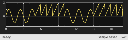
Simulate the model and observe the Scope block display. In the first five seconds, the Merge block output is the same as the top subsystem output. Between t = 5 s and t = 10 s, the Merge block output matches the bottom subsystem when the top subsystem is not active.
See Also
Merge | Repeating Sequence | Data Type Conversion | Logical Operator | Pulse Generator | Level-2 MATLAB S-Function

