La traduction de cette page n'est pas à jour. Cliquez ici pour voir la dernière version en anglais.
Signaux
Les signaux transmettent des données entre deux blocs dans une simulation. Ces données peuvent correspondre à la sortie calculée d'un bloc ou à un simple message. La valeur du signal est calculée tout au long de la simulation. Vous pouvez afficher les données et les propriétés des signaux pendant et après la simulation, visualiser les valeurs en temps réel sur un schéma bloc ou les enregistrer en tant que variables dans l'espace de travail. Vous pouvez également exporter les signaux dans un fichier ou un espace de travail pour les étudier plus en détail.
Vous pouvez contrôler le comportement mathématique d'un modèle en spécifiant les caractéristiques des signaux telles que le type de données numériques, la valeur initiale et la plage de valeurs. Pour plus d’informations, consultez Signal Basics.
Blocs
Fonctions
Objets
sltrace.Graph | Signal path traced using sltrace function (depuis R2021b) |
Outils
| Signal Properties | View and edit signal properties |
| Instrumentation Properties | View and edit logging and visualization properties for logged signal |
| Property Inspector | Edit parameters and properties for any Simulink model element |
| Model Data Editor | Inspect and edit data items (signals, parameters, and states) in a table that you can sort, group, and filter |
| Component Interface View | Display component interfaces to trace port connections and author ports |
Paramètres du modèle
Rubriques
En savoir plus sur les signaux
- Signal Basics
Create, configure, identify, and test signals. - Signal Types
Learn about different types of signals, such as control signals and composite signals. - Signal Groups
Test or debug models by creating interchangeable groups of signal data.
Propriétés des signaux
- Investigate Signal Values
Initialize, access, and view the values that signals have during a simulation run. - Specify Signal Ranges
Specify the minimum and maximum value that a signal can attain during simulation. Fully specify your design and optimize data types and the generated code by specifying the minimum and maximum value that a signal can attain during simulation. - Determine Signal Dimensions
Inspect and control signal dimensionality. - How Simulink Propagates Signal Properties in a Model
Inspect how Simulink® propagates signal properties in a model. - Initialize Signals and Discrete States
Some systems contain signals and states whose initial values you must specify, for example, the starting position and velocity of a bouncing ball. - Configure Signals as Test Points
Use test points to exclude signal lines from optimizations which enables you to access the simulation data. - Specify Common Set of Signal Properties as Value Type
Create a reusable value type for common signal properties, such as the application-specific signal properties of wind velocity. (depuis R2021b)
Afficher les propriétés des signaux
- Highlight Signal Sources and Destinations
Trace a signal to its source or destination while debugging or exploring a model. - View Signal Values Using Port Value Labels
View signal values in the block diagram during simulation to understand, analyze, and debug your model. - Display Signal Attributes
Improve model readability by displaying signal attributes, such as data types and dimensions, in the block diagram. - Signal Label Propagation
Name a signal to identify and access it more easily. Take advantage of signal label propagation to reduce the effort of naming a signal that crosses system boundaries. - Trace Connections and Author Ports Using Component Interface View
Display component interfaces to trace port connections and author ports.
Signaux de taille variable
- Variable-Size Signal Basics
Create a variable-size signal whose size and values can change during a simulation. - Inspect Variable-Size Signals on Simulink Models
Inspect example models that show how to use variable-size signals. - Unbounded Variable-Size Signals
Model unknown size data using dynamic arrays.
Informations connexes
Sélection d՚exemples
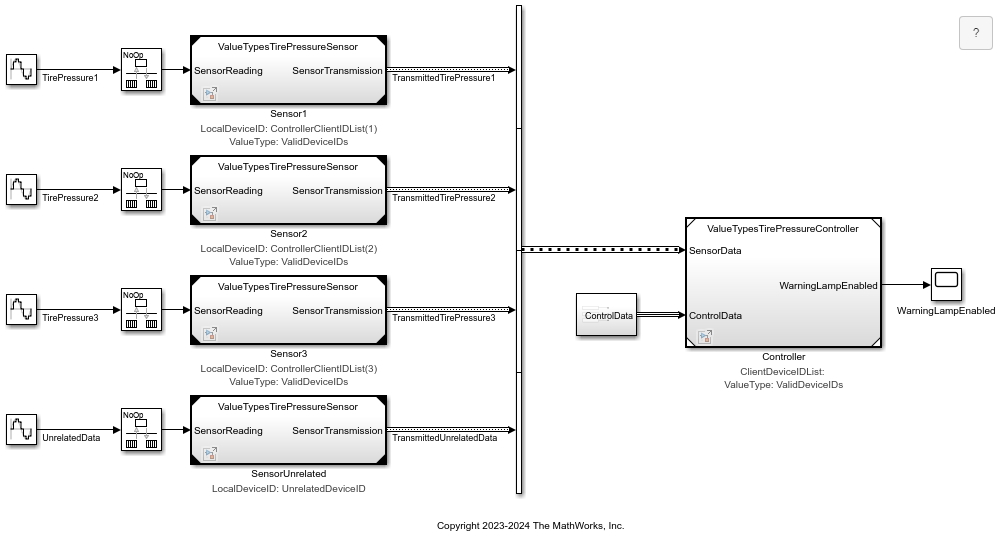
Value Types at Component Interfaces
Assign a meaningful name to a set of properties at an interface and reuse that set of properties with value types.
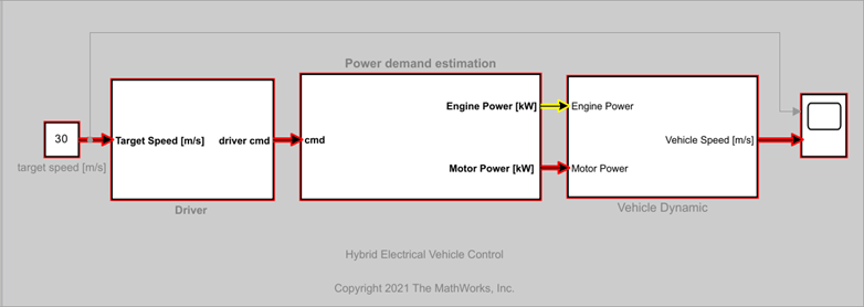
Find Shortest Control Path in Simulink Model
How to find the shortest control path for a hybrid electrical vehicle using Signal Tracing Command-line API.

Arithmetic Operations on Matrix Signals
Perform arithmetic operations on signals carrying matrix and vector data.

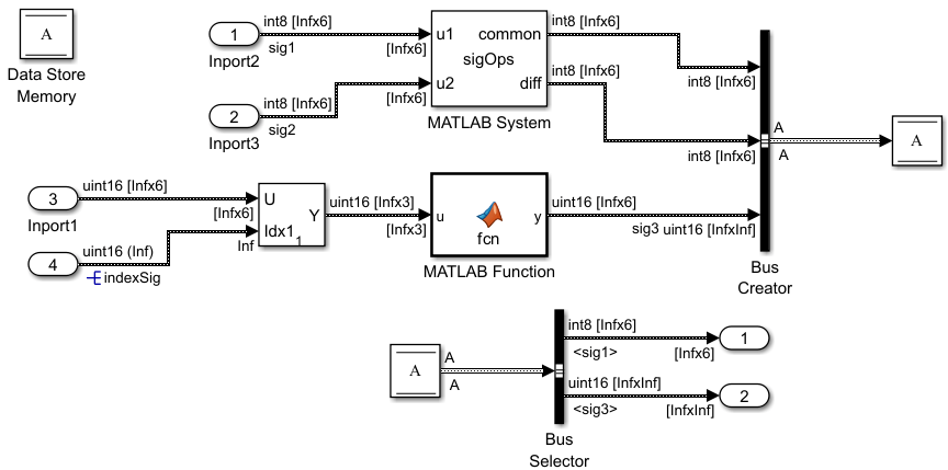
Bounded Variable-Size Signal Basic Operations
Generate bounded variable-size signals and illustrates some of the operations using those signals. In this example, you generate variable-size signals using the Selector block and the Switch block. The signals are used in math operations, bus creation, bus selection, matrix concatenation and to implement a discrete filter equation.
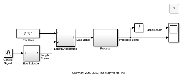
Variable-Size Signal Length Adaptation
Model showing how to change the length of a signal over time.

Multimode Variable-Size Signal
Use different operation modes to correspond to different signal sizes.

Merging Signals
Use conditionally executed subsystems and the Merge block to combine two inputs into a single output.
Unbounded Variable-Size Signal Basic Operations
Use unbounded variable-size signals in Simulink® modeling. For more information about the general concept of unbounded variable-size signals, see Unbounded Variable-Size Signals.

Use Unbounded Variable-Size Signals between Model Components
Use unbounded variable-size signals to handle unbounded-size data between different model components. The example also shows how to prepare the model for C++ code generation.