Map Signal Data to Root Input Ports
After you import data, map signal data to root input ports by selecting map modes and options and selecting data.
For a summary of the other steps involved in using the Root Inport Mapper tool, see Import and Mapping Workflow.
Select Map Mode
To map signal data to root-level ports, use one of these map modes in the Map Configuration section of the Root Inport Mapper toolstrip. The map mode you select from the toolstrip, such as Block Name or Port Order, is maintained between MATLAB® sessions and models. You do not have to select the map mode each time you want to map signal data to root input ports.
For more information on map modes, see Root Inport Mapper.
Set Options for Mapping
If you want to set up mapping options, in the Map Configuration section on the Root Inport Mapper toolstrip, click Options. The option you select from the toolstrip, such as Update Model Automatically or Allow Partial Specification of Buses, is maintained between MATLAB sessions and models. You do not have to select the option each time you want to map signal data to root inports.
To map the signals, see Map Data.
Select Data to Map
To specify a subset of scenarios to map, click the down arrow on the Check Map Readiness button. The default behavior of the Check Map Readiness button defaults to the last Check Map Readiness option selected.
You can choose different map modes for different scenarios. For more information on map modes, see Root Inport Mapper.
Map Data
After you import signals or buses, you can map data.
On the Root Inport Mapper toolbar, to check if a data set is mappable, click Check Map Readiness.
You can then select another map mode and check the readiness again. The results of a signal mapping appear in the Scenario Dataset tab.
If the map mode is not compatible with the mapping, Root Inport Mapper displays a message, such as:
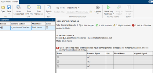
You can then select another map mode and check the readiness again.
In the left pane, click a data set to see the mapping results
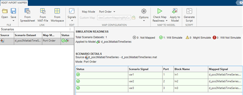
The Simulation Readiness section lists the input data and the status of the mapping.
Note
The mapping definition for the input data is applied to the model.
After you save and close the model, when you load input data of the same scenario to the workspace, the model uses the mapping defined for that scenario.
For an example of mapping signal data to root-level inputs, see Create Harness-Free Models with MAT File Input Data.
After you save the mapping definition for a model, you can automate data loading. For more information, see Alternative Workflows to Load Mapping Data.
Understand Mapping Results
When you complete the import and map process, the Simulation Readiness section displays the results in the status area. The results depend on whether you select the Update Model Automatically option when you set up the mapping.
| Status | Update Model Automatically | Continue Without Update Model Automatically |
|---|---|---|
The properties of the mapped data and the input port are appropriate for simulation. | The data type, dimension, and signal type properties of the data and input port are compatible. | |
Not applicable | Comparison of data and root-level port data type, dimension, and signal type properties cannot determine whether there is a match. If you do not update the model before mapping, the tool cannot evaluate whether all the data types match unless you explicitly specify the input port data types. Confirm that you set these block parameters correctly: Inport
block parameter Data type is not set to
Inport
block parameter Dimension is not set to
Inport
block parameter Signal type cannot be
| |
The properties of the mapped data and the input port are not appropriate for simulation. | One or more of the data types, dimensions, or signal types of the signal data are not compatible with the root-level input port. |
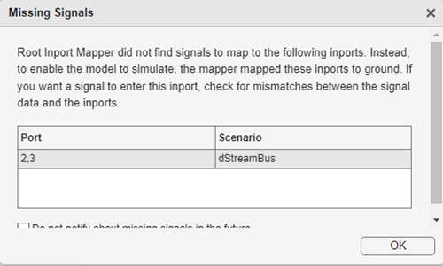
To enable the model to simulate, if Root Inport Mapper does not find input port
signals to map, it maps these input ports to ground and displays a Missing
Signals dialog box. An input port mapped to a ground signal displays as
empty ([]).
This figure shows mapping successes, failures, and ground assignments. If there are issues, the status column displays suggested resolutions. Read through and diagnose the issues.
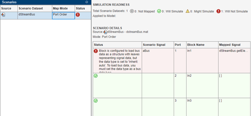
Sometimes the Simulation Readiness section shows a warning or error, but your investigation of the elements indicates that there is no problem with mapping the data. In these cases, if you did not select the Update Model Automatically check box from the Options menu, select it and click Check Map Readiness again.
In the Root Inport Mapper tool, clicking Apply to Model selects the Input check box in the Data Import/Export pane in the model Configuration Parameters dialog box. It also sets the value to the imported data variables. To apply the changes to the model configuration, in the Data Import/Export pane, click OK. Clicking Apply to Model also automatically identifies the first scenario to map.
If your model uses configuration references to reference configuration sets, you cannot mark the model for simulation. To use this data to simulate the model with the Root Inport Mapper tool, use the Model Explorer to activate a configuration set first.
This graphic illustrates the application of the changes to the model configuration for the model in Map Data.
![]()
To inspect the imported data, you can:
Connect the output to a scope, simulate the model, and observe the data.
Log the signals and use the Simulation Data Inspector tool to observe the data.
To highlight the Inport block that is associated with the signal, select an item in the Simulation Readiness section. The selected Inport block is outlined with blue.
Note
When the input is a bus, click the levels of the bus object to see the individual elements in the bus.
Alternative Workflows to Load Mapping Data
After you save the mapping definition to a model, you can automate data loading and simulation. Consider one of the following methods.
Command Line or Script
To load data and simulate the model from the MATLAB command line, use commands similar to:
load('signaldata.mat');
simout = sim('model_name');
To automate testing and load different signal groups, consider using a script.
The following example code creates timeseries data and simulates a model after loading each signal group. It:
Creates signal groups with variable names In1, In2, and In3, and saves these variables to MAT files.
Simulates a model after loading each signal group.
Note
The variable names must match the import data variables in the Configuration Parameters > Data Import/Export > Input parameter.
% Create signal groups
fileName = 'testCase';
for k =1 :3

    % Create the timeseries data
    var1 = timeseries(rand(10,1));
    var2 = timeseries(rand(10,1));
    var3 = timeseries(rand(10,1));

    %create a dataset
    ds = Simulink.SimulationData.Dataset();
    ds = ds.addElement( var1, 'var1');
    ds = ds.addElement( var2, 'var2');
    ds = ds.addElement( var3, 'var3');

    % Save the data
    save([fileName '_' num2str(k) '.mat' ],'ds');
end
clear all

% After mapping and saving the model loop over signal groups and simulate
% Set the filename to append testcase # to
fileName = 'testCase';
% Loop backwards to preallocate
for k=3:-1:1
   % Load the MAT file.
   load([fileName '_' num2str(k) '.mat']);

   % Simulate the model
   simOut{k} = sim('model_name');
end
Use the PreLoadFcn Model Callback
When you are satisfied with the data and mapping, you can configure your model to
load a MAT file containing the signal group into the MATLAB workspace. Call the load function in the
PreLoadFcn callback for the model.
After saving the MAT file, on the Modeling tab, click the Model Settings drop-down and select Model Properties.
In the Model Properties window, select the Callbacks tab and then the
PreLoadFcnnode.Enter a command to load the MAT file containing the signal data. For example:
load d_signal_data.mat;
Click OK and save the model.