Simplify Subsystem and Model Interfaces with Bus Element Ports
Buses simplify the interfaces of components, such as subsystems and models, by letting you associate multiple signals or messages with one port. They reduce line complexity and clutter in a block diagram, make it easier to change the interface incrementally, and allow access to elements closer to their point of usage.
When you first define a component interface or add a port to an existing component interface, consider using buses. To create bus element ports at component interfaces, see Group Signals or Messages into Virtual Buses.
For an overview of how to use buses to simplify component interfaces, see Reduced Bus Wiring: Bus Element Ports (2 min, 7 sec).
For an example of how buses can simplify component interfaces, this model contains subsystems that have multiple input and output ports.

This equivalent model uses buses, and each subsystem has one input and output port.

For buses at component interfaces:
Use In Bus Element blocks instead of Inport and Bus Selector blocks.
Use Out Bus Element blocks instead of Bus Creator and Outport blocks.
In Bus Element and Out Bus Element blocks support
multirate virtual buses and do not require Simulink.Bus objects at
model interfaces, unlike Inport and Outport blocks. They
also provide cleaner bus interfaces.
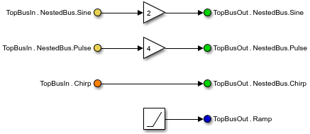
For example, this model uses Inport, Bus Selector, Bus Creator, and Outport blocks.
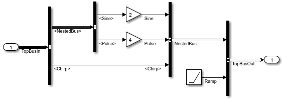
This equivalent model uses In Bus Element and Out Bus Element blocks.

At the interface you want to update:
Remove signal logging, test points, and descriptions from the lines that the conversion removes. For example, the line between a Bus Creator block and an Outport block must not be designated as a test point.
Remove conflicting specifications. For example, when you specify a
Simulink.Busobject as the data type of an output port, each element of the output port must inherit its data type from theSimulink.Busobject.
The following examples demonstrate how to update interfaces to use In Bus Element and Out Bus Element blocks. The example models are simple, however, buses are most useful when you have many elements to combine.
Combine Multiple Subsystem Ports into One Port
This example shows three ways to simplify a subsystem interface by converting multiple ports and their connected signals into one port and a bus. Model interfaces do not support this automated conversion.
Open the example model, which contains two subsystems with multiple input and output ports.
mdl = "VirtualBusPortCreation";
open_system(mdl);
Drag a selection box around the signal lines between the two subsystems. From the action bar that appears, click Create Bus.
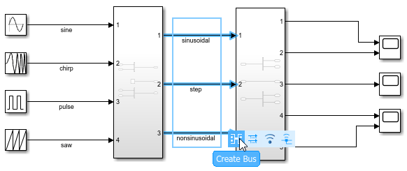
Simulink® replaces the Inport and Outport blocks in the source and destination subsystems with In Bus Element and Out Bus Element blocks.
Drag a selection box around the signal lines between the source blocks and first subsystem. From the action bar that appears, click Create Bus.
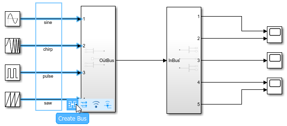
Simulink adds a Bus Creator block before the first subsystem and replaces the Inport blocks in the first subsystem with In Bus Element blocks.
Drag a selection box around the signal lines between the second subsystem and Scope blocks. From the action bar that appears, click Create Bus.
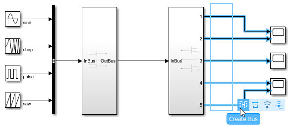
Simulink replaces the Outport blocks in the second subsystem with Out Bus Element blocks and adds a Bus Selector block after the second subsystem.
The resulting model uses virtual buses at the subsystem interfaces.

Simplify Bus Interfaces in Subsystems and Models
This example shows how to convert a subsystem or model interface that uses Inport, Bus Selector, Bus Creator, and Outport blocks to use In Bus Element and Out Bus Element blocks.
Open the BusInterfaceConversion model. To update the line styles, in the Simulink® Toolstrip, on the Modeling tab, click Update Model or Run. Updating the line styles can help you visually identify buses.
mdl = "BusInterfaceConversion";
open_system(mdl)
set_param(mdl,SimulationCommand="Update")
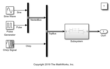
Double-click the Subsystem block.

In the subsystem, Inport and Outport blocks represent the subsystem input and output. Bus Selector and Bus Creator blocks modify the input bus hierarchy.
To convert Inport and Bus Selector blocks to In Bus Element blocks:
Click a Bus Selector block that directly connects to an Inport block.
In the action bar that appears when you pause on the ellipsis, click Bus Ports.
For example, click the top-level Bus Selector block. Then, click Bus Ports.

In this example, the bus between the Inport block and top-level Bus Selector block has a signal label. The conversion uses the signal label as the name of the new bus element port.
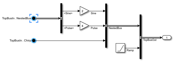
When an Inport block has nondefault parameter values, the conversion applies the nondefault parameter values to the top-level element of the bus element port.
You can similarly convert In Bus Element and Bus Selector blocks. To convert In Bus Element and Bus Selector blocks to In Bus Element blocks:
Click a Bus Selector block that directly connects to an In Bus Element block.
In the action bar that appears when you pause on the ellipsis, click Bus Ports.
For example, click the remaining Bus Selector block. Then, click Bus Ports.

To convert Bus Creator and Outport blocks to Out Bus Element blocks:
Click a Bus Creator block that directly connects to an Outport block without branching.
In the action bar that appears when you pause on the ellipsis, click Bus Ports.
For example, select the top-level Bus Creator block. Then, click Bus Ports.

In this example, the bus between the top-level Bus Creator block and Outport block has a signal label. The conversion uses the signal label as the name of the new bus element port.

When an Outport block has nondefault parameter values, the conversion applies the nondefault parameter values to the top-level element of the bus element port.
You can similarly convert Bus Creator and Out Bus Element blocks. To convert Bus Creator and Out Bus Element blocks to Out Bus Element blocks:
Click a Bus Creator block that directly connects to an Out Bus Element block.
In the action bar that appears when you pause on the ellipsis, click Bus Ports.
For example, click the remaining Bus Creator block. Then, click Bus Ports.

The resulting model simplifies line routing, makes it easier for you to incrementally change the interface, and lets you access elements closer to their point of usage.

To further simplify your block diagram, consider moving the blocks.
To change the name of a bus or element, double-click and edit the corresponding part of the block label.
To easily identify elements of the same port or nested bus, specify block colors.
Double-click an In Bus Element or Out Bus Element block to open the dialog box for the related port.
Select an element or the top bus.
Click
 . Then, select a background color.