Simulate Actor Movement Using Simulink
This example shows how you can control an actor in the Unreal Engine® visualization environment through Simulink®. The Unreal Engine and Simulink communicate with each other during each simulation step through the co-simulation framework. To control an actor in the Unreal Engine® visualization environment through MATLAB®, see Simulate Actor Movement Using MATLAB.
The Simulation 3D Scene Configuration block sets up the co-simulation framework between the Unreal Engine and Simulink and the Simulation 3D Actor block builds an actor. You can control the actor movement in the Unreal Engine visualization environment using Simulink blocks and view the animation in the Simulation 3D Viewer. You can also capture the actor image from any viewpoint using a camera sensor.
Open Model
Open the Simulink model.
open_system("CosimulateWithUE");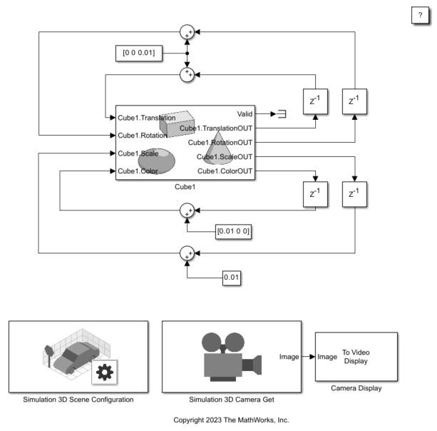
Explore Model Components
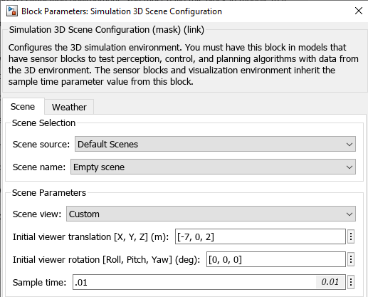
The main model components include a Simulation 3D Scene Configuration block, a Simulation 3D Actor block, and a Simulation 3D Camera Get block. The Simulation 3D Scene Configuration block implements a 3D simulation environment. Double-click the Simulation 3D Scene Configuration block to open the Block Parameters dialog box. Set a view in the scene with the Scene view parameter. You can also set a custom viewpoint with this parameter. You must include the configuration block when building Simulink models with Simulation 3D Actor blocks.
The Simulation 3D Actor block adds an actor to the 3D environment. Double-click the Simulation 3D Actor block to open the Block Parameters dialog box. To create an actor before simulation starts, on the Main tab, set Operation to Create at setup. The block first creates an empty actor with the name specified in the Actor name parameter. You can use any name for the actor. Then, the block loads the source file, if any is present, and runs the Initialization script. For more details, see Operating Modes. The Initialization script builds a box shape for the actor Cube1 using the createShape function. Specify the size and color of the actor in the Initialization script text box.

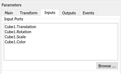
You can use input and output ports to control the actor during simulation. On the Inputs and Outputs tabs, click Browse to add input and output ports to the actor block, respectively.

The output ports feed back to the input ports with delay units and Sum blocks to vary the translation, rotation, scale, and color of the actor during each simulation step. The changing values of the properties animates the actor in the Unreal Engine.
The Simulation 3D Camera Get block outputs the images captured during the simulation. The block outputs the camera display using a To Video Display (Computer Vision Toolbox) block.
Simulate Model
Simulate the model and view the animation of the cube in the Simulation 3D Viewer.
sim("CosimulateWithUE");
You can also view the Camera Display behind the Simulation 3D Viewer window.

Close Model
Close the Simulink model.
close_system("CosimulateWithUE");See Also
Simulation 3D Actor | Simulation 3D Scene Configuration | Simulation 3D Camera Get