Resolver Peripheral Configuration
Description
View and edit the map of peripherals in the Infineon® AURIX™ model to the hardware peripherals.
Using the Hardware Mapping tool, you can:
View and edit configuration parameters of the Resolver peripheral block.
Check for any conflicts between the peripherals.

Open the Resolver Peripheral Configuration
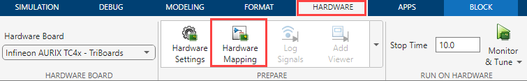
In the Hardware tab, click Hardware Mapping.
Parameters
Carrier wave — Option to enable carrier wave for excitation
on
(default) | off
Enable to configure excitation carrier waveform parameters.
Waveform — Excitation carrier waveform
Sine
(default) | Square | Triangle
Specify the type of excitation carrier waveform.
Dependencies
To enable this parameter, select the Carrier wave parameter.
Carrier wave frequency in KHz — Frequency of excitation carrier waveform
9.762
(default) | 78.1 | 39.05 | 26.03 | 19.52 | 15.62 | 13.01 | 11.15 | 8.677 | 7.810 | 7.100 | 6.508 | 6.007 | 5.578 | 5.206 | 4.881
Specify the frequency of excitation carrier waveform.
Dependencies
To enable this parameter, select the Carrier wave parameter.
Select positive pwm pin — Positive PWM pin for carrier excitation
P33_12
(default) | P02_1 | P00_6
Select positive PWM pin for carrier excitation.
Dependencies
To enable this parameter, select the Carrier wave parameter.
Select negative pwm pin — Negative PWM pin for carrier excitation
P33_11
(default) | P02_0 | P00_5
Select negative PWM pin for carrier excitation.
Dependencies
To enable this parameter, select the Carrier wave parameter.
Output mode — Output mode for PWM pin
Push pull
(default) | Open-drain
Select output mode of the PWM pin for carrier excitation.
Dependencies
To enable this parameter, select the Carrier wave parameter.
Speed — Speed for PWM pin
Speed-1
(default) | Speed-2 | Speed-3
Select speed of the PWM pin for carrier excitation.
Dependencies
To enable this parameter, select the Carrier wave parameter.
Voltage level — Voltage level for PWM pin
Automotive
(default) | TTL-5V | TTL-3.3V
Select voltage level of the PWM pin for carrier excitation.
Dependencies
To enable this parameter, select the Carrier wave parameter.
Bit reverse mode — Option to enable bit reverse mode
off
(default) | on
Select to enable bit reverse mode for excitation carrier waveform.
Dependencies
To enable this parameter, select the Carrier wave parameter.
Inverted polarity — Option to enable inverted polarity
off
(default) | on
Select to enable inverted polarity for excitation carrier waveform.
Dependencies
To enable this parameter, select the Carrier wave parameter.
Maximum count for voltage reference (1-32768) — Maximum count for full-scale voltage
25000
(default) | scalar in the range (1, 32768)
Maximum count for full-scale voltage.
On-chip modulator frequency (MHz) — Select the on-chip modulator frequency
20
(default) |
40
|
10
Select the on-chip modulator frequency.
Note
The available options vary based on the value of External oscillator (MHz). Click Model Settings and navigate to Configuration Parameters > Hardware Implementation > Target hardware resources > Clocking > External oscillator (MHz) in the Simulink® model to change its value.
Dithering — Option to add dithering
Disable
(default) |
Level-0
|
Level-1
|
Level-2
|
Level-3
Add dithering (white noise), if required.
Enable auto calibration — Option to enable auto calibration
off
(default) |
on
Enable auto calibration of the delta-sigma conversion.
Calibration type — Calibration type for the delta-sigma conversion
High precision
(default) |
High Speed
Specify the type of calibration for the delta-sigma conversion.
Dependencies
To enable this parameter, select the Enable auto calibration parameter.
Positive input type — Type of positive input
Input-pin
(default) |
Ground
Type of positive input of the sine channel for delta-sigma conversion.
Note
The resolver module supports differential inputs where you can configure positive and negative inputs accordingly. In case of a single-ended application, you can configure the unused pin to the ground.
Select positive pin — Pin number of positive pin
AN20
(default) | pin numbers
Select pin number of the sine channel positive pin.
Dependencies
To enable this parameter, set the Positive input type
parameter to Input-pin.
Negative input type — Type of negative input
Ground
(default) |
Input-pin
Type of negative input of the sine channel for delta-sigma conversion.
Select negative pin — Pin number of negative pin
AN21
(default) |
AN25/P40_1
Select pin number of the sine channel negative pin.
Dependencies
To enable this parameter, set the Negative input type
parameter to Input-pin.
Positive input type — Type of positive input
Input-pin
(default) |
Ground
Type of positive input of the cosine channel for delta-sigma conversion.
Note
The resolver module supports differential inputs where you can configure positive and negative inputs accordingly. In case of a single-ended application, you can configure the unused pin to the ground.
Select positive pin — Pin number of positive pin
AN12
(default) | pin numbers
Select pin number of the cosine channel positive pin.
Dependencies
To enable this parameter, set the Positive input type
parameter to Input-pin.
Negative input type — Type of negative input
Ground
(default) |
Input-pin
Type of negative input of the cosine channel for delta-sigma conversion.
Select negative pin — Pin number of negative pin
AN13
(default) |
AN3
Select pin number of the cosine channel negative pin.
Dependencies
To enable this parameter, set the Negative input type
parameter to Input-pin.
Input mode — Input mode for resolver pin
Tri-state
(default) |
Pull-up
|
Push-down
Select the input mode for the resolver pin(s).
Speed — Speed for resolver pin
Speed-1
(default) |
Speed-2
|
Speed-3
Select the pin speed for the resolver pin.
Voltage level — Voltage level for resolver pin
Automotive
(default) |
TTL-5V
|
TTL-3.3V
Select the voltage level for the resolver pin.
Decimation factor (3-1023) — Decimation factor for conversion
64
(default) | scalar in the range (3, 1023)
Decimation factor for delta-sigma conversion. Higher the value of Decimation factor, higher will be the accuracy, at the cost of additional time.
Enable offset compensation — Offset compensation for delta-sigma conversion
off
(default) |
on
Enable offset compensation for delta-sigma conversion.
Cutoff frequency — Cutoff frequency for offset compensation
0
(default) |
0 to 7
Cutoff frequency for offset compensation.
Dependencies
To enable this parameter, select the Enable offset compensation parameter.
Offset in volts (0-5) — Offset voltage
0
(default) |
0 to 5
Specify the offset voltage in volts.
Dependencies
To enable this parameter, select the Enable offset compensation parameter.
Sign-signal source — Sign signal source for excitation carrier
On-chip carrier generator
(default) |
Channel result
|
External
                        pin
Select the sign signal source for the excitation carrier.
carrier frequency in KHz (1-1000) — Specify the carrier frequency
9.762
(default) |
1 to 1000
Specify the carrier frequency for the rectifier channel.
Dependencies
To enable this parameter, set the Sign-signal source
parameter to Channel result or External
pin.
Sign source pin — Select sign source pin
P32_7
(default) |
P33_13
Select external source pin for the sign-signal.
Dependencies
To enable this parameter, set the Sign-signal source
parameter to External pin.
Auto assign sign-delays — Option to automatically assign sign delays
on
(default) |
off
Enable to automatically assign sign delays.
Sine channel delay in seconds (0-0.0016) — Sine channel delay
0
(default) | scalar in the range (0, 0.0016)
Specify the delay of sine channel.
Dependencies
To enable this parameter, select the Auto assign
sign-delays parameter.
Cosine channel delay in seconds (0-0.0016) — Cosine channel delay
0
(default) | scalar in the range (0, 0.0016)
Specify the delay of cosine channel.
To enable this parameter, select the Auto assign
sign-delays parameter.
Number of values to discard (0-127) — Number of values to discard during integration
0
(default) | scalar in the range (0, 127)
Specify the number of values to discard during integration.
Number of carrier cycles to integrate — Number of carrier cycles to integrate
1
(default) | option varies based on the value of decimation factor and on-chip modulator
frequency parameters
Specify the number of carrier cycles to integrate.
Number of values for accumulation — Number of samples selected for integration
default depends on value of Number of carrier cycles to integrate
parameter
This is a read only parameter, which indicates the number of samples selected based on the Number of carrier cycles to integrate parameter.
Timestamp frequency (MHz) — Frequency of timestamp measurement
20
(default) |
10
|
5
|
2.5
Specify the frequency of timestamp.
Dependencies
To enable this parameter, set the Enable timestamp parameter in the Resolver block in the Simulink model.
Gate source to trigger timestamp — Hardware trigger source for timestamp
GTM-ATOM0
(default) |
GTM-ATOM#
|
GTM-TOM#
|
EGTM-ATOM#
|
EGTM-TOM#
Specify the hardware trigger source for timestamp.
Note
Ensure that you have configured the appropriate trigger from the PWM block with a rate (1/initial clock frequency of PWM) that must be greater than or equal to 4 times the Output rate in seconds parameter tab in Resolver Peripheral Configuration tool. This is due to the availability of two results, one for each sine and cosine channels.
Dependencies
To enable this parameter, select the Enable timestamp parameter in the Resolver block in the Simulink model.
Hardware trigger — Hardware trigger for timestamp
Options vary based on the value of gate source to trigger timestamp parameter
Specify the type of hardware trigger for timestamp.
Dependencies
To enable this parameter, select theEnable timestamp parameter in the Resolver block in the Simulink model.
Trigger edge — Hardware trigger edge
Rising-edge
(default) |
Falling-edge
|
Both-edges
Specify hardware trigger edge for timestamp.
Dependencies
To enable this parameter, select the Enable timestamp parameter in the Resolver block in the Simulink model.
Trigger delay in nano seconds (0-409593) — Trigger delay for timestamp
0
(default) | scalar in the range (0, 409593)
Specify the trigger delay for timestamp.
Dependencies
To enable this parameter, select theEnable timestamp parameter in the Resolver block in the Simulink model.
Output rate in seconds — Minimum rate at which the resolver module updates the output
value depends on other parameters (default)
This a read only parameter indicating the minimum rate at which the resolver module updates the output. Its value depends on On-chip modulator frequency (MHz), Decimation factor (3-1023), and Number of values for accumulation parameters.
Dependencies
To enable this parameter, select theEnable timestamp parameter in the resolver block in the Simulink model.
Lower limit in volts (-5V to 5V) — Lower limit for the boundary band
0
(default) | scalar in the range (-5, 5)
Specify the lower limit for the boundary band for checking the result.
Upper limit in volts (-5V to 5V) — Upper limit for the boundary band
5
(default) | scalar in the range (-5, 5)
Specify the upper limit for the boundary band for checking the result.
Enable hysteresis on boundary flag — Option to enable hysteresis on boundary flag
off
(default) |
on
Enable hysteresis to avoid metastable states and switching due to internal ground bounce.
Boundary flag — Boundary mode for sine channel
Disabled
(default) |
Exceeds upper limit
|
Lower than lower limit
|
Out of
                        bound
Specify boundary mode for the sine channel.
Dependencies
To enable this parameter, select the Enable hysteresis on boundary flag parameter.
Service request — Service request based on the boundary mode
None
(default) |
Inside boundary band
|
Outside boundary band
Specify the service request based on the boundary mode.
Number of connections — Number of boundary flag connections
0
(default) | scalar in the range (0, 32)
Specify the number of boundary flag connections for the sine channel.
Dependencies
To enable this parameter, set the Boundary flag
parameter to Inside boundary band,
Outside boundary band, or Out of
bound.
Module — Module for boundary flag connections
default value varies on the value of number of connections
parameter (default) | GTM - TOM# |
GTM - ATOM# |
EGTM - TOM# |
EGTM - ATOM#
Specify the module for boundary flag connections.
Dependencies
To enable this parameter, set the Number of connections parameter to a value greater than 0.
Channel(s) — Channels for boundary flag connections
0-3
(default) |
4-7
Specify the channels for boundary flag connections.
Dependencies
To enable this parameter, set the Number of connections parameter to a value greater than 0.
Lower limit in volts (-5V to 5V) — Lower limit for the boundary band
0
(default) | scalar in the range (-5, 5)
Specify the lower limit for the boundary band for checking the result.
Upper limit in volts (-5V to 5V) — Upper limit for the boundary band
5
(default) | scalar in the range (-5, 5)
Specify the upper limit for the boundary band for checking the result.
Enable hysteresis on boundary flag — Enable hysteresis on boundary flag
off
(default) |
on
Enable hysteresis to avoid metastable states and switching due to internal ground bounce.
Boundary flag — Boundary mode for cosine channel
Disabled
(default) |
Exceeds upper limit
|
Lower than lower limit
|
Out of
                        bound
Specify the boundary mode for cosine channel.
Dependencies
To enable this parameter, set the Enable hysteresis on boundary flag parameter.
Service request — Service request based on the boundary mode
None
(default) |
Inside boundary band
|
Outside boundary band
Specify service request based on the boundary mode.
Number of connections — Number of boundary flag connections
0
(default) | scalar in the range (0,32)
Specify the number of boundary flag connections for the cosine channel.
Dependencies
To enable this parameter, set the Boundary flag
parameter to Inside boundary band,
Outside boundary band, or Out of
bound.
Module — Module for boundary flag connections
Default value varies on the Number of connections
                     parameter
(default) |
GTM - TOM# | GTM - ATOM# | EGTM - TOM# |
EGTM - ATOM#
Specify the module for boundary flag connections.
Dependencies
To enable this parameter, set the Number of connections parameter to a value greater than 0.
Channel(s) — Channels for boundary flag connections
0-3
(default) |
4-7
Specify the channels for boundary flag connections.
Dependencies
To enable this parameter, set the Number of connections parameter value as greater than 0.
Enable interrupt — Enable interrupt for main filter
off
(default) |
on
Enable interrupt for main filter.
Channel — Interrupt channel for main filter
Sine
(default) |
Cosine
Specify interrupt channel for the main filter
Dependencies
To enable this parameter, set the Enable interrupt parameter.
Interrupt — Interrupt condition for main filter
Always
(default) |
Only while gate is high
|
Only
                        while gate is low
Specify interrupt condition for the main filter. To limit the conversion interrupts, select the gate-signal option.
Dependencies
To enable this parameter, set the Enable interrupt parameter.
Gate signal from — Source of gate signal to trigger the main filter result
Carrier Generator
(default) |
GTM-TOM#
|
GTM-ATOM#
|
EGTM-ATOM#
|
EGTM-TOM#
Specify the source of the gate signal to trigger the main filter result.
Note
Ensure that you have configured the appropriate trigger using the PWM block.
Dependencies
To enable this parameter, set the Interrupt parameter
to Only while gate is high or Only
while gate is low.
Hardware trigger — Hardware trigger for main filter result
options vary based on the value of Gate signal from parameter
Hardware trigger for the main filter result.
Dependencies
To enable this parameter, set the Interrupt parameter
to Only while gate is high or Only
while gate is low.
Trigger delay in nano seconds (0-409593) — Trigger delay for main filter result
0
(default) | scalar in the range (0, 409593)
Trigger delay for the main filter result.
Dependencies
To enable this parameter, set the Interrupt parameter
to Only while gate is high or Only
while gate is low.
Enable interrupt — Enable interrupt for timestamp
off
(default) |
on
Enable interrupt for timestamp.
Channel — Interrupt channel for the timestamp
Sine
(default) |
Cosine
Specify interrupt channel for the timestamp.
Dependencies
To enable this parameter, set the Enable interrupt parameter.
Version History
Introduced in R2024a
See Also
Commande MATLAB
Vous avez cliqué sur un lien qui correspond à cette commande MATLAB :
Pour exécuter la commande, saisissez-la dans la fenêtre de commande de MATLAB. Les navigateurs web ne supportent pas les commandes MATLAB.
Select a Web Site
Choose a web site to get translated content where available and see local events and offers. Based on your location, we recommend that you select: .
You can also select a web site from the following list:
How to Get Best Site Performance
Select the China site (in Chinese or English) for best site performance. Other MathWorks country sites are not optimized for visits from your location.
Americas
- América Latina (Español)
- Canada (English)
- United States (English)
Europe
- Belgium (English)
- Denmark (English)
- Deutschland (Deutsch)
- España (Español)
- Finland (English)
- France (Français)
- Ireland (English)
- Italia (Italiano)
- Luxembourg (English)
- Netherlands (English)
- Norway (English)
- Österreich (Deutsch)
- Portugal (English)
- Sweden (English)
- Switzerland
- United Kingdom (English)