Integrator (Discrete or Continuous)
Discrete-time or continuous-time integrator
Libraries:
Simscape /
Electrical /
Control /
General Control
Description
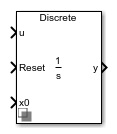
The Integrator (Discrete or Continuous) block implements a simple integrator in conformance with IEEE 421.5-2016[1].
You can switch between continuous and discrete implementations of the integrator using the Sample time (-1 for inherited) parameter.
Equations
To configure the integrator for continuous time, set the Sample time
(-1 for inherited) property to 0. This
representation is equivalent to the continuous transfer function:
From the preceding transfer function, the integrator defining equations are:
where:
u is the integrator input.
x is the integrator state.
y is the integrator output.
t is the simulation time.
x0 is the initial state of the integrator.
To configure the integrator for discrete time, set the Sample time
(-1 for inherited) property to a positive, nonzero value, or to
-1 to inherit the sample time from an upstream block. The
discrete representation is equivalent to the transfer function:
where Ts is the sample time.
This block can integrate or accumulate a signal
using a forward Euler, backward Euler, or trapezoidal method. To specify the
integration or accumulation method of the block, use the
Integrator method parameter. (since R2025a) If you set
the Integrator method parameter to
Integration: Forward Euler, the block defines the
integrator equations using the forward Euler method from the discrete transfer function:
where:
u is the integrator input.
x is the integrator state.
y is the integrator output.
n is the simulation time step.
x0 is the initial state of the integrator.
Defining Initial Conditions
You can define the state initial conditions using the input port x0. The integrator state reverts to the initial condition any time it is reset.
Limiting the Integral
You can limit the integral output using one of two methods:
Set Limit type to
Anti-windupto use the anti-windup saturation method.The anti-windup method limits the integrator state x between the lower saturation limit A and upper saturation limit B:
Because the state is limited, the output can respond immediately to a reversal of the input sign when the integral is saturated.
Set Limit type to
Windupto use the windup saturation method.The windup method limits the integrator output y between the lower saturation limit A and upper saturation limit B:
Because the output is limited, the state can continue to grow when the integrator is saturated. As a result, the output cannot respond to a reversal of the input sign until the state has reached the limiting saturation point.
Resetting the State
You can reset the state of the integrator by passing a nonzero signal to the Reset port of the block.
Ports
Input
Output
Parameters
References
[1] IEEE Recommended Practice for Excitation System Models for Power System Stability Studies. IEEE Std 421.5-2016. Piscataway, NJ: IEEE-SA, 2016.