OFDM Receiver Using Software-Defined Radio
R2026bThis example shows how to design an orthogonal frequency division multiplexing (OFDM) receiver for a single-input single-output (SISO) channel using a software-defined radio (SDR). The OFDM receiver captures and demodulates the OFDM signal that the OFDM Transmitter Using Software-Defined Radio example sends. The OFDM receiver design includes sample buffering for timing adjustment, filtering, carrier frequency adjustment, and OFDM demodulation.
Required Hardware and Software
To run this example, you need one of these SDRs and the corresponding software support package.
USRP™ N2xx and B2xx series radio and Communications Toolbox Support Package for USRP Radio. For information on supported radios, see Supported Hardware and Required Software.
USRP E3xx, N3xx, X3xx, or X4xx series radio and Wireless Testbench Support Package for NI USRP Radios. For information on supported radios, see Supported Radio Devices (Wireless Testbench).
ADALM-PLUTO radio and Communications Toolbox Support Package for Analog Devices® ADALM-PLUTO Radio.
The example requires two MATLAB™ sessions, one for the transmitter and one for the receiver. You run the OFDM Transmitter Using Software-Defined Radio example in one MATLAB session to transmit the OFDM signal.
Choose the OFDM Frame Parameters
Choose the OFDM parameters according to your baseband sample rate by selecting the appropriate OFDM Waveform index from the table
OFDM Waveform Index | 1 | 2 |
|---|---|---|
Baseband sample rate | 3.84 Msps | 7.68 Msps |
FFT Length | 128 | 256 |
Cyclic Prefix Length | 32 | 64 |
Number of Subcarriers | 90 | 180 |
Subcarrier Spacing | 30 KHz | 30 KHz |
Pilot Subcarrier Spacing | 9 | 20 |
Channel Bandwidth | 3 MHz | 6 MHz |
Note that the baseband sample rate is derived as .
After selecting the OFDM parameters, you must set the data parameters such as modulation order, code rate, number of symbols per frame, and the number of frames per transmission.
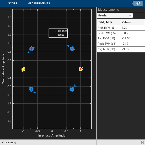
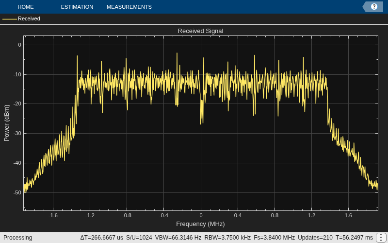
You can enable or disable the visualization scopes. However, for long simulations, it is recommended to disable the scope. To control the display of the diagnostic output text, enable or disable the verbosity as needed. To view the decoded data in each frame, enable the print data flag. To view the error vector magnitude (EVM) and peak-to-average power ratio (PAPR) for each frame, enable the corresponding flags.
% Choose the OFDM waveform parameters according to your baseband sample % rate and provide the corresponding OFDMWaveformIndex from the table above OFDMWaveformIndex =1; % Data Parameters dataParams.modOrder =
4; % Data modulation order dataParams.coderate =
"1/2"; % Code rate dataParams.numSymPerFrame =
30; % Number of data symbols per frame dataParams.numFrames =
45; % Number of frames to transmit % Output Parameters dataParams.enableScopes =
true; % Switch to enable or disable the visibility of scopes dataParams.verbosity =
false; % Control to print the output diagnostics at each level of receiver processing dataParams.printData =
false; % Control to print the output decoded data dataParams.enableEVMCalculation =
false; % Switch to enable or disable EVM calculation dataParams.enablePAPRCalculation =
false; % Switch to enable or disable PAPR calculation
Initialize Receiver Parameters
Use the helperOFDMSetParamsSDR function to initialize the OFDM transmit parameters and the common transmitter/receiver settings needed for the simulation. Then call helperGetRadioRxObj to initialize the parameters required for the receiver System object™ radio.
Set the radio address, center frequency, gain, and the sample rate at which the radio captures data.
By default, the example uses burst mode for reception using USRP or ADALM‑PLUTO radios, since streaming mode processing can cause receive overflows at higher data rates.
If the receiving radio device is a USRP radio, you can enable reception in streaming mode by setting enableRxStreamingInBackground to true. USRP radios support background processing. When enableRxStreamingInBackground is set to true, radio reception runs in the background while received data processing executes in the foreground. This separation reduces the processing load on a single execution thread and can help minimize receive overflows in streaming mode and also achieve higher sample rates.
radioParams.RadioDevice ="B210"; % Choose radio device for reception radioParams.RadioAddress =
'30F597A'; % update radio address radioParams.CenterFrequency =
3e9; % Center Frequency radioParams.Gain =
60; % Set radio gain radioParams.EnableRxStreamingInBackground =
false; % Enable the flag to receive data in background in streaming mode
If you use an X3xx radio with a TwinRX daughterboard, set the isTwinRxDaughterBoard option to true inside helperGetRadioRxObj to ensure proper channel mapping and synchronization.
Note that the radio receives the OFDM waveform at a higher sample rate and resamples it to baseband sample rate using the resampling factors provided by helperGetRadioRxObj.
Finally, initialize the system parameters and receiver objects.
[sysParams,txParam,transportBlk] = helperOFDMSetParamsSDR(OFDMWaveformIndex,dataParams);
[radio, spectrumAnalyze, constDiag, resampleNum, resampleDen] = helperGetRadioRxObj(radioParams,sysParams);
Execute Receiver Loop
Synchronization
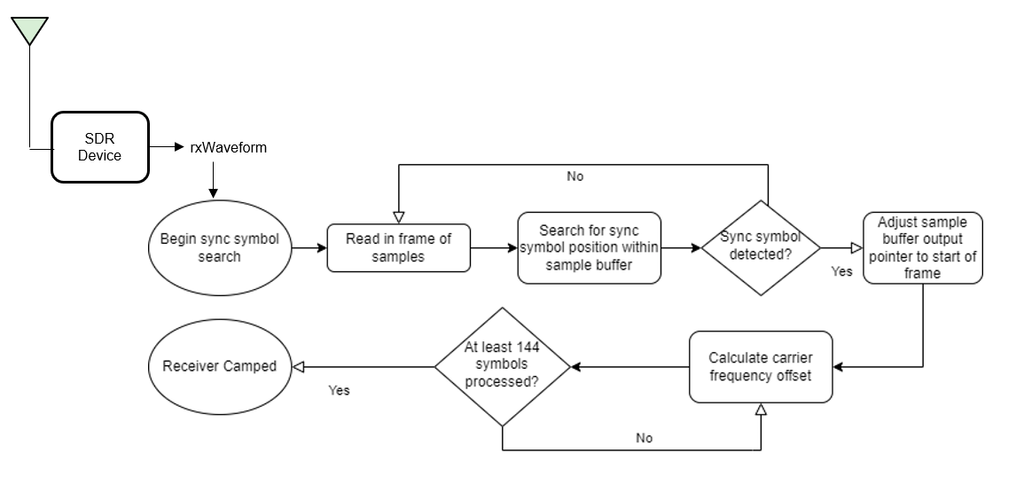
The OFDM receiver checks the sample buffer for the synchronization symbol to find the starting point of the data frames within the received OFDM signal. The receiver correlated the received OFDM signal with the known synchronization symbol. Once the OFDM receiver detects a high correlation peak, it identifies the position where it finds the synchronization symbol as the start of the frame.
Frequency Offset Estimation and Correction
The OFDM receiver estimates and corrects the frequency and timing offset introduced to the transmitted OFDM signal due to channel impairments. The OFDM receiver checks the receiver buffer for the required number of frames and performs automatic frequency correction over each symbol. The receiver averages the frequency correction across the subcarriers and then across every six symbols, considering a group of six symbols as a slot. The receiver considers the overall average value of these corrections as the frequency offset and compensates this frequency offset across the entire frame.
The receiver is considered camped after achieving successful synchronization and channel impairment correction.
Receiver Processing
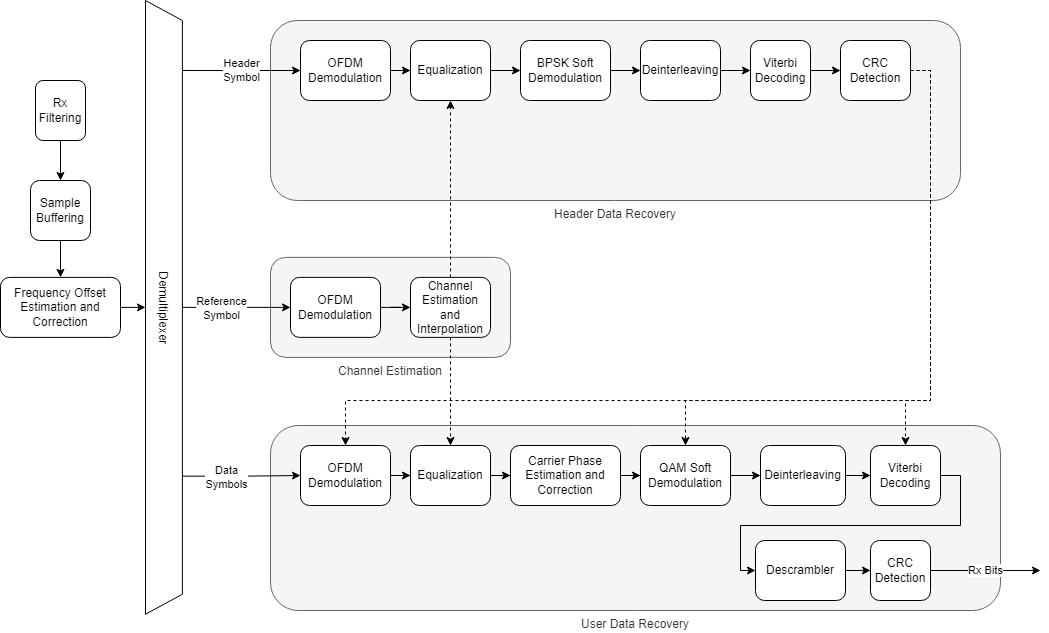
This process is the reverse of the process that happens at the transmitter.
Channel Estimation and Equalization
Initially, the OFDM receiver performs channel estimation on the OFDM demodulated reference symbols. To remove the effects of time-varying fading, the receiver selects two reference symbols from adjacent frames to estimate the channel at two different points in time. The receiver then linearly interpolates the channel estimates between the two reference symbols to get the channel estimates for the header and data symbols. The ofdmEqualize function then equalizes the reference symbols and data symbols using the channel estimates.
Header Decoding
The receiver extracts and decodes the header symbols to get the data symbol parameters such as FFT length, subcarrier modulation scheme, and code rate. The receiver uses these parameters to demodulate and decode the data symbols.
Data Decoding
The common phase error (CPE) affects all subcarriers equally and the OFDM receiver uses the pilot symbols within the data symbols to estimate CPE. The helperOFDMRx function corrects the phase errors in the data symbols and the qamdemod function soft decodes the data subcarriers into log likelihood ratios (LLRs).
The receiver then deinterleaves the demodulated bitstream and the vitdec function performs maximum likelihood decoding using the Viterbi algorithm. The descrambler descrambles the decoded bits, and the crcDetect computes the cyclic redundancy check (CRC) and compares it with the appended CRC.
% Clear all the function data as they contain some persistent variables
clear helperOFDMRx helperOFDMRxFrontEnd helperOFDMRxSearch helperOFDMFrequencyOffset;
close all;
errorRate = comm.ErrorRate();
toverflow = 0; % Receiver overflow count
rxObj = helperOFDMRxInit(sysParams);
BER = zeros(1,dataParams.numFrames);

% Perform radio reception in the background and store data in a dataQueue
% continuously. Retrieve the data frame-by-frame from the queue to base
% workspace sequentially as after each reception
if radioParams.EnableRxStreamingInBackground && ~strcmpi(radioParams.RadioDevice,'PLUTO')
    dataQueue = parallel.pool.PollableDataQueue;
    pool = backgroundPool;
    future = parfeval(pool, @receiveData, 0, radio, dataQueue, dataParams.numFrames);
end

for frameNum = 1:dataParams.numFrames
    sysParams.frameNum = frameNum;
    if radioParams.EnableRxStreamingInBackground && ~strcmpi(radioParams.RadioDevice,'PLUTO')
        if frameNum == 1
            [data, ok] = poll(dataQueue, 30);
        else
            [data, ok] = poll(dataQueue, 3);
        end
        if ~ok
            if ~isempty(future.Error)
                error('Background receiver failed: %s', future.Error.message);
            else
                warning('Timeout waiting for chunk %d of sweep %d', chunkIdx, sweepIdx);
                continue;
            end
        end
        rxWaveform = data.rxWaveform;
        overflow = data.overflow;
    else
        % Receive data in burst mode otherwise
        [rxWaveform, ~, overflow] = radio();
    end

    % Resample the waveform to baseband sample rate
    rxWaveform = resample(rxWaveform,resampleNum,resampleDen);

    toverflow = toverflow + overflow;

    % Run the receiver processing only when there is no overflow
    if ~overflow

        rxIn = helperOFDMRxFrontEnd(rxWaveform,sysParams,rxObj);

        % Run the receiver processing
        [rxDataBits,isConnected,toff,rxDiagnostics] = helperOFDMRx(rxIn,sysParams,rxObj);

        sysParams.timingAdvance = toff;
        if toff<0
            sysParams.timingAdvance = sysParams.txWaveformSize;
        end

        % Collect bit and frame error statistics
        if isConnected
            % Continuously update the bit error rate using the |comm.ErrorRate|
            % System object
            berVals = errorRate(...
                transportBlk((1:sysParams.trBlkSize)).', ...
                rxDataBits);
            BER(frameNum) = berVals(1);
            if dataParams.printData
                % As each character in the data is encoded by 7 bits, decode the received data up to last multiples of 7
                numBitsToDecode = length(rxDataBits) - mod(length(rxDataBits),7);
                recData = char(bit2int(reshape(rxDataBits(1:numBitsToDecode),7,[]),7));
                fprintf('Received data in frame %d: %s',frameNum,recData);
            end
        end

        if isConnected && dataParams.enableScopes
            constDiag(complex(rxDiagnostics.rxConstellationHeader(:)), ...
                complex(rxDiagnostics.rxConstellationData(:)));
        end

        if isConnected && dataParams.enableEVMCalculation
            evm = helperCalculateEVM(complex(rxDiagnostics.rxConstellationData(:)),dataParams.modOrder);
            fprintf('RMS Error Vector Magitude(EVM) of received OFDM symbols is %.2f',evm);
        end

        if isConnected && dataParams.enablePAPRCalculation
            pm = powermeter(Measurement="Peak-to-average power ratio");
            pm.WindowLength = length(rxDiagnostics.rxConstellationData(:));
            pm.OverlapLength = 0;
            papr = pm(complex(rxDiagnostics.rxConstellationData(:)));
            fprintf('PAPR of received OFDM symbols is %.2f dB',papr);
            release(pm);
        end

        if dataParams.enableScopes
            spectrumAnalyze(rxWaveform);
        end
    else
        % Clear all the data buffers, reset the timing advance value and perform re-synchronization if
        % there is an overflow
        clear helperOFDMRx helperOFDMRxFrontEnd helperOFDMRxSearch;
        disp("Overflow at frame: "+frameNum);
        sysParams.timingAdvance = sysParams.txWaveformSize;
    end
end
Sync symbol found.
Estimating carrier frequency offset ........
Receiver synchronization complete.
......................................
% Display the mean BER value across all frames
fprintf('Simulation complete!\nAverage BER = %d',mean(BER))
Simulation complete!
Average BER = 0
release(radio);
Local Functions
When the receiver is a USRP device, data reception can run in the background while the receiver operates in streaming mode. The receiveData function executes asynchronously in a background thread to continuously fetch samples from the radio. This function places the received data into a data queue.
In the foreground, you can retrieve the data from the data queue sequentially by calling the storeData function
% Run the radio reception in background and send the received data frames
% into a queue
function receiveData(radio,queue,numFrames)
    for i = 1:numFrames
        [data,~,ov] = radio();
        rxData.rxWaveform = data;
        rxData.overflow = ov;
        rxData.frameNum = i;
        send(queue,rxData);
    end
end
Troubleshooting
No data in any frame
Problem
The receiver continuously receives no data in any frame.
Possible causes
Transmitter is not running
Too high or too low transmitter and receiver gains
Too many under-runs at the transmitter
Possible solutions
Ensure that the transmitter is running
Adjust the transmitter and receiver gains
Adjust the frame length to make sure there are very few under-runs at the transmitter.
Header CRC fails
Problem
Even when synchronization and receiver camping are successful, the header CRC check fails.
Possible causes
Insufficient compensation of clock frequency offset.
Possible solutions
The frequency compensation algorithm measures and corrects the frequency and phase offset for each frame, and it can estimate the correct offset up to half of the subcarrier spacing. You can calibrate the frequency offset to resolve this error.
For USRP radios, you can determine the frequency offset by sending a tone at a known frequency from the transmitter and measure the offset between the transmitted and received frequency. Apply the measured offset to the center frequency of comm.SDRuReceiver receiver System object.
For ADALM-Pluto radios, run the Frequency Offset Calibration with ADALM-PLUTO Radio in Simulink example to get the frequency offset. Apply the measured offset to the center frequency of the comm.SDRRxPluto receiver System object.
Data decoding fails
Problem
The data decoding fails even when the header CRC decoding is successful.
Possible causes
Data overflow at the receiver
Inaccurate channel estimate due to exceeding frame length.
Possible solutions
Adjust the frame size
Change the number of symbols per frame to minimize the frame length.
Further Exploration
You can use an external clock source or GPSDO with the radios to try smaller subcarrier spacing of 15 KHz with smaller bandwidths such as 1.4 MHz (LTE bandwidths) or higher FFTLengths such as 512.
This example uses burst mode in the radios to receive the data, with the burst size set to the number of frames. You can further explore receiving the data using the radios in non-burst mode.
See Also
Topics
- OFDM Transmitter and Receiver
- HDL OFDM MATLAB References (Wireless HDL Toolbox)
- HDL OFDM Receiver (Wireless HDL Toolbox)

