OFDM Transmitter Using Software-Defined Radio
R2026bThis example shows how to design an orthogonal frequency division multiplexing (OFDM) transmitter for a single-input single-output (SISO) channel using a software-defined radio (SDR).
This example details the physical-layer transmission protocol of the OFDM system that mimics typical synchronization signals, reference symbols, control channels, and data channels. The OFDM transmission system processing includes cyclic redundancy check (CRC), encoding, scrambling, convolutional encoding, modulation, and filtering.
The OFDM Receiver Using Software-Defined Radio example receives and demodulates the OFDM signal transmitted by this example.
Required Hardware and Software
To run this example you will need one of the following hardware and the corresponding support package
USRP™ N2xx and B2xx series radio and Communications Toolbox Support Package for USRP Radio. For information on supported radios, see Supported Hardware and Required Software.
USRP E3xx, N3xx, X3xx, or X4xx series radio and Wireless Testbench Support Package for NI USRP Radios. For information on supported radios, see Supported Radio Devices (Wireless Testbench).
ADALM-PLUTO radio and Communications Toolbox Support Package for Analog Devices® ADALM-PLUTO Radio.
Choose the OFDM Frame Parameters
Choose the OFDM parameters according to your baseband sample rate by selecting the appropriate OFDM waveform index from the table.
OFDM Waveform Index | 1 | 2 |
|---|---|---|
Baseband Sample Rate | 3.84 Msps | 7.68 Msps |
FFT Length | 128 | 256 |
Cyclic Prefix Length | 32 | 64 |
Number of Subcarriers | 90 | 180 |
Subcarrier Spacing | 30 KHz | 30 KHz |
Pilot Subcarrier Spacing | 9 | 20 |
Channel Bandwidth | 3 MHz | 6 MHz |
Note that the baseband sample rate is derived as .
After configuring the OFDM parameters, you must set the data parameters such as modulation order, code rate, number of symbols per frame, and the number of frames per transmission. The possible modulation schemes are BPSK, QPSK, 16-QAM and 64 QAM and the possible code rates are 1/2 and 2/3. The OFDM parameters and the data parameters must be common to both transmitter and receiver.
You can enable or disable the scopes for visualization, however for long simulations, it is recommended to disable the scope. To control the diagnostic output, enable or disable the verbosity as needed.
% Choose the OFDM waveform parameters according to your baseband sample % rate and provide the corresponding OFDMWaveformIndex from the table above OFDMWaveformIndex =1; % Data Parameters dataParams.modOrder =
4; % Data modulation order dataParams.coderate =
"1/2"; % Code rate dataParams.numSymPerFrame =
30; % Number of data symbols per frame 20 dataParams.numFrames =
10000; % Number of frames to transmit dataParams.enableScopes =
true; % Switch to enable or disable the visibility of scopes dataParams.verbosity =
false; % Switch to enable or disable the data diagnostic output
Initialize Transmitter Parameters
Assign the name of the radio you are using for transmitting the OFDM signal to the variable RadioDevice. Set the receiver gain and operating center frequency.
radioParams.RadioDevice ="B210"; % Choose the radio device for transmission radioParams.RadioAddress =
'3136D08'; % update radio address radioParams.CenterFrequency =
3e9; % Center Frequency radioParams.Gain =
60; % Set radio gain
The helperOFDMSetParamsSDR function initializes transmit-specific and common transmitter/receiver parameters required for the OFDM simulation and the helperGetRadioTxObj function initializes the parameters required for the radio transmitter System object™.
The OFDM waveform uses a baseband rate of 3.84 Msps or 7.68 Msps. When the transmitter radio cannot operate directly at this rate, such as with an N2xx device, the example configures the transmitter to operate at higher sample rate instead. The waveform is resampled to baseband sample rate after reception.
[sysParams,txParam,trBlk] = helperOFDMSetParamsSDR(OFDMWaveformIndex,dataParams);
basebandSampleRate       = sysParams.FFTLen * sysParams.scs;
% Get the radio transmitter and spectrum analyzer system object for the user to visualize the transmitted waveform.
[radio,spectrumAnalyze] = helperGetRadioTxObj(radioParams,sysParams);
Generate Transmitter Waveform
Transmit Frame Structure
A transport block contains user data and control information. The OFDM transmitter transmits one transport block per frame. The transport block size varies based on several factors: the number of active subcarriers, the number of pilot subcarriers, modulation order, coding rate, CRC length, encoder constraint length, and the number of data symbols per frame.
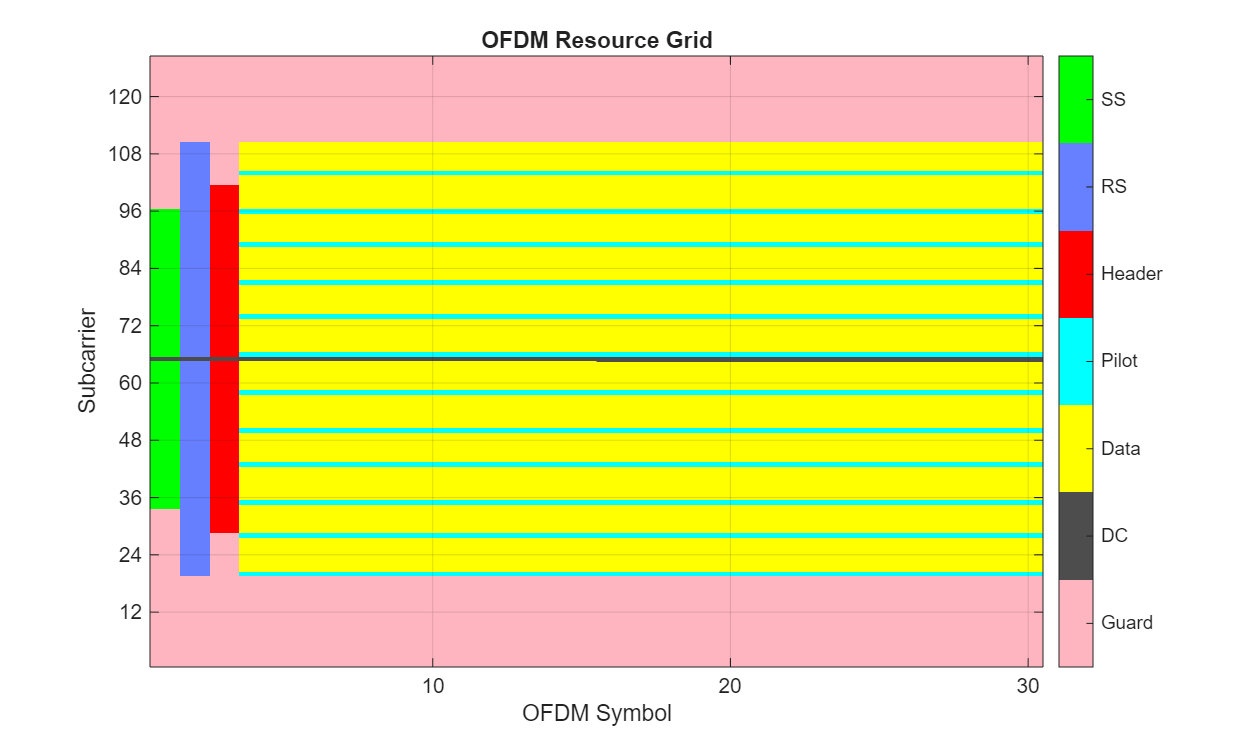
The transmission grid populates signals and channels on a per-frame basis. The figure below shows one transmission frame of 28 OFDM symbols with FFT length of 128.
Synchronization Symbol (SS)
A synchronization (sync) signal is transmitted as the first symbol in the frame. The sync signal consists of a 62-subcarriers signal centered at DC generated using a Zadoff-Chu. This signal is designed to be bandwidth agnostic, meaning that all transmitters can transmit this signal regardless of the allocated bandwidth for that cell. The signal is meant to be detected by receivers to positively detect the cell signal and identify the frame boundary (the start of the frame).
Reference Symbol (RS)
The next symbol in the transmit frame is the reference symbol. Known at both the transmitter and receiver, the reference symbol allows the receiver to compare the received reference symbol with the known reference symbol to estimate the channel. The receiver then compensates for the channel distortion between the transmitter and receiver.
Header Symbol
The header symbol conveys the bandwidth, subcarrier modulation scheme, and code rate of the OFDM data symbols to help the receiver decode the transmitted frame. The information is important enough that it is transmitted with large signaling and coding margins to maximize correct decoding. Therefore, the symbol is coded at 1/2 rate with wide interleaving and modulated using BPSK. Since the channel distortion may change over time, the header symbol is transmitted immediately after the reference symbol to maximize the probability of correct reception. Because the bandwidth is not yet known, the header is always transmitted with a 72-subcarrier signal centered at DC.
Pilot Signals
Finally, to combat phase jitter seen at higher transmission frequencies, a pilot is transmitted at fixed subcarrier intervals within the data symbols to provide a phase reference to the receiver.
DC and Guard Subcarriers
Null subcarriers at the edge of the transmission spectrum are used to constrain spectral energy to a specified bandwidth. The subcarrier at DC is also nulled to keep the signal energy to within the linear range of the power amplifier.
Transmitter processing
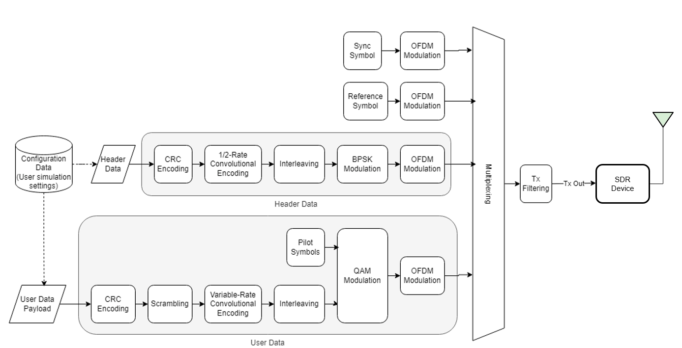
The data symbols comprise a single user populating a single transport block of data transmitted once per frame. A crcGenerate object computes the CRC for the transport block payload and appends it to the payload. The data is additively scrambled using a comm.PNSequence object to distribute the data power evenly across the transmission spectrum. Interleaving is done with the reshape function to resist burst errors caused by deep fades. Convolutional encoding adds redundant bits for forward error correction and is done with the convenc function. Puncturing of the data increases data throughput by reducing the number of redundant bits. The transport block is modulated using the qammod function and is ready for transmission in an OFDM frame. All signals are OFDM-modulated using the ofdmmod function. The signal is filtered to reduce out-of-band emissions using dsp.FIRFilter, with coefficients generated using the firpmord and firpm filter design functions.
% Initialize transmitter
txObj = helperOFDMTxInit(sysParams);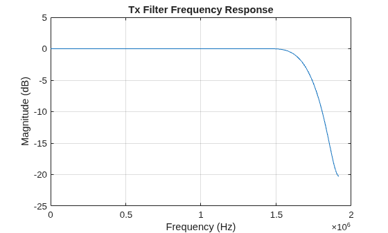
tunderrun = 0; % Initialize count for underruns

% A known payload is generated in the function helperOFDMSetParams with
% respect to the calculated trBlkSize
% Store data bits for BER calculations
txParam.txDataBits = trBlk;
[txOut,txGrid,txDiagnostics] = helperOFDMTx(txParam,sysParams,txObj);

% Display the grid if verbosity flag is enabled
if dataParams.verbosity
    helperOFDMPlotResourceGrid(txGrid,sysParams);
end

txOutSize = length(txOut);
if contains(radioParams.RadioDevice,'PLUTO') && txOutSize < 48000
    % Repeat the data in a buffer for PLUTO radio to make sure there are less
    % underruns. The receiver decodes only one frame from where the first
    % synchronization signal is received
    frameCnt = ceil(48000/txOutSize);
    txWaveform = zeros(txOutSize*frameCnt,1);
    for i = 1:frameCnt
        txWaveform(txOutSize*(i-1)+1:i*txOutSize) = txOut;
    end
elseif contains(radioParams.RadioDevice,'N200/N210/USRP2')
    % Resample the data to 5 Msps before transmission
    txWaveform= resample(txOut,125,96);
else
    txWaveform = txOut;
end

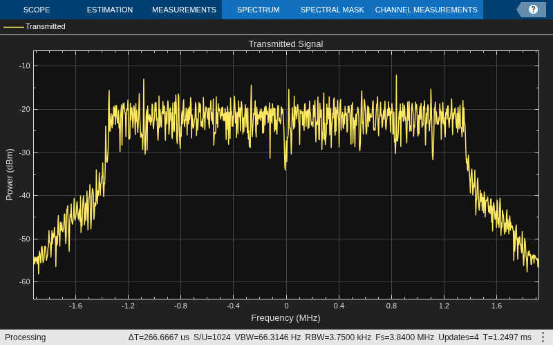
if dataParams.enableScopes
spectrumAnalyze(txOut);
end
Transmit Over Radio
for frameNum = 1:sysParams.numFrames
underrun = radio(txWaveform);
    tunderrun = tunderrun + underrun;  % Total underruns
end
linux; GNU C++ version 14.3.0; Boost_108500; UHD_4.9.0.0-0-unknown

---------- see libuhd version information above this line ----------
% Clean up the radio System object
release(radio);
Further Exploration
You can modify the initialization parameters in the helperOFDMSetParamsSDR and helperOFDMTxInit functions. Similarly, you can modify helperOFDMPilotSignal, helperOFDMRefSignal, and helperOFDMSyncSignal helper functions to generate custom pilot, reference and synchronization signals respectively.
See Also
Topics
- OFDM Transmitter and Receiver
- HDL OFDM MATLAB References (Wireless HDL Toolbox)
- HDL OFDM Receiver (Wireless HDL Toolbox)

