Clock, Reset, and Enable Signals
Driving Clocks, Resets, and Enables
You can create rising-edge or falling-edge clocks, resets, or clock enable signals that apply internal stimuli to your model under cosimulation. You can add these signals by:
Creating Optional Clocks with the Clocks Pane of the HDL Cosimulation Block
Implementing these signals directly in HDL code. If your model is part of a much larger HDL design, you (or the larger model designer) may choose to implement these signals in the Verilog® or VHDL® files. However, that implementation exceeds the scope of this documentation; see an HDL reference for more information.
Adding Signals Using Simulink Blocks
Add rising-edge or falling-edge clocks, resets, or clock enable signals to your Simulink® model using Simulink blocks. See the Simulink User Guide and Reference for instructions on adding blocks to a model.
In the following example excerpt, the shaded area shows a clock, a reset, and a clock enable signal as input to a multiple HDL Cosimulation block model. These signals are created using two Simulink data type conversion blocks and a constant source block, which connect to the HDL Cosimulation block labeled "Manchester Receiver Subsystem".

Creating Optional Clocks with the Clocks Pane of the HDL Cosimulation Block
Note
For ModelSim™ and Xcelium™ users only.
When you specify a clock in your block definition, Simulink creates a rising-edge or falling-edge clock that drives the specified HDL signal.
Simulink attempts to create a clock that has a 50% duty
cycle and a predefined phase that is inverted for the falling edge
case. If applicable, Simulink degrades the duty cycle to accommodate
odd Simulink sample times, with a worst case duty cycle of 66%
for a sample time of T=3.
Whether you have configured the Timescales pane for relative timing mode or absolute timing mode, the following restrictions apply to clock periods:
If you specify an explicit clock period, you must enter a sample time equal to or greater than 2 resolution units (ticks).
If the clock period (whether explicitly specified or defaulted) is not an even integer, Simulink cannot create a 50% duty cycle, and therefore the HDL Verifier™ software creates the falling edge at
(rounded down to the nearest integer).
For more information on calculating relative and absolute timing modes, see Defining the Simulink and HDL Simulator Timing Relationship.
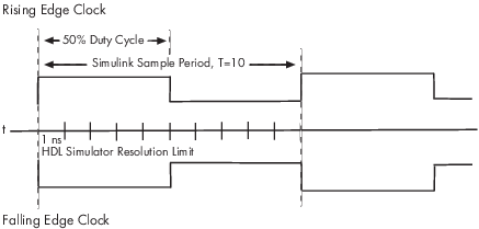
The following figure shows a timing diagram that includes rising
and falling edge clocks with a Simulink sample time of T=10 and
an HDL simulator resolution limit of 1 ns. The figure also shows that
given those timing parameters, the clock duty cycle is 50%.
To create clocks, perform the following steps:
In the HDL simulator, determine the clock signal path names you plan to define in your block. To do so, you can use the same method explained for determining the signal path names for ports in step 1 of “Map HDL Signals to Block Ports”.
Select the Clocks tab of the Block Parameters dialog box.
Click New to add a new clock signal.
Edit the clock signal path name directly in the table under the Full HDL Name column by double-clicking the default clock signal name (
/top/clk). Then, specify your new clock using HDL simulator path name syntax. See Specify HDL Signal/Port and Module Paths for Simulink Testbench Cosimulation.The HDL simulator does not support vectored signals in the Clocks pane. Signals must be logic types with 1 and 0 values.
To specify whether the clock generates a rising-edge or falling edge signal, select
RisingorFallingfrom the Active Clock Edge list.The Period field specifies the clock period. Accept the default (
2), or override it by entering the desired clock period explicitly by double-clicking in the Period field.Specify the Period field as an even integer, with a minimum value of
2.When you have finished editing clock signals, click Apply to register your changes with Simulink.
The following dialog box defines the rising-edge clock clk for the
HDL Cosimulation block, with a default period of 2 (example shown
for use with Xcelium).

Driving Signals by Adding Force Commands
You can drive clocks, resets, and enable signals in either of two ways:
By adding force commands to the Simulation pane (ModelSim and Xcelium users only)
By driving signals with one of the HDL Verifier HDL simulator launch commands (
vsimornclaunch) and the force command
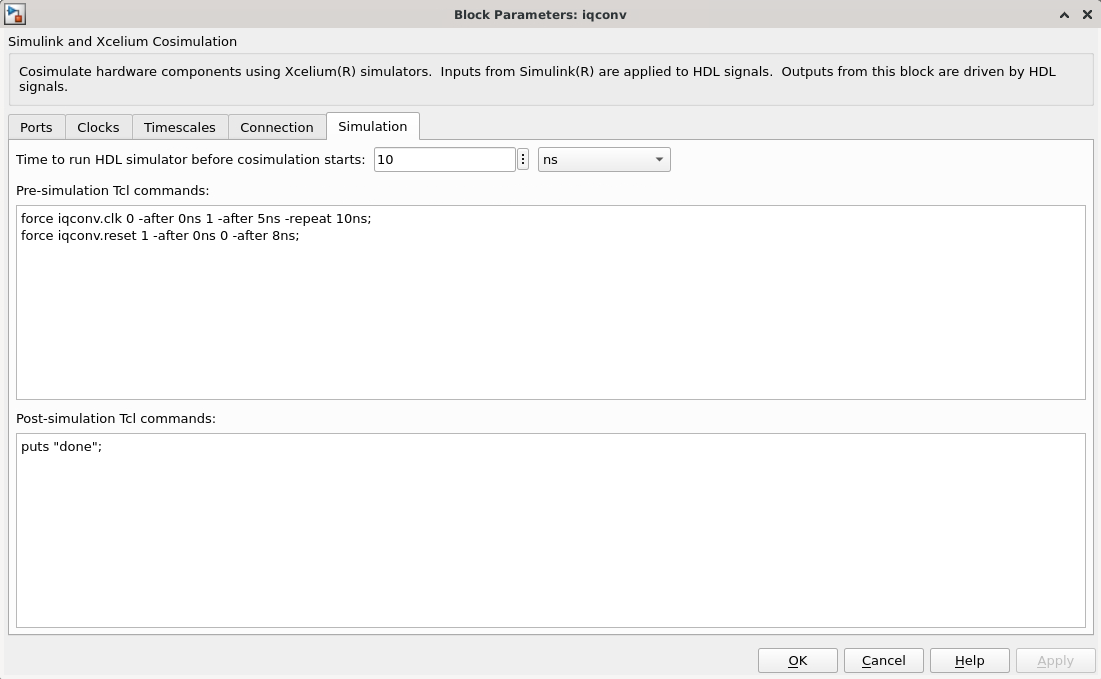
Examples: force Command entered in HDL Cosimulation block Simulation Pane
The following is an example of entering force commands in the Simulation pane of the HDL Cosimulation block for use with Xcelium:
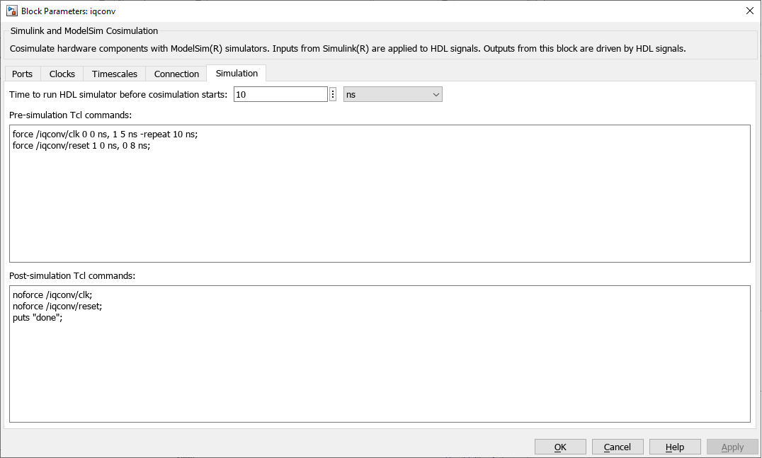
The following is an example of entering force commands in the Simulation pane of the HDL Cosimulation block for use with ModelSim:
Examples: force Command used with HDL Verifier HDL Simulator Launch Command
vsim function and force command (ModelSim users):
vsim('tclstart', {'force /iqconv/clk 0 0, 1 5 ns -repeat 10 ns',
                  'force /iqconv/reset 1 0 ns, 0 8 ns'});
nclaunch function and force command (Xcelium users):
nclaunch('tclstart',['-input "{force iqconv.clk 0 -after 5ns -repeat 10ns}"',
                     '-input "{force iqconv.reset 1 -after 0ns 0 -after 8ns}"',]);