Create a Simulink Cosimulation Testbench
These steps describe how to cosimulate an HDL design using Simulink® software as a testbench.
Create a Simulink testbench model by adding Simulink blocks from the Simulink block libraries. Run and test your model thoroughly before replacing or adding hardware model components as cosimulation blocks.
Code HDL module. Compile, elaborate, and simulate your module in your HDL simulator. See Code an HDL Component.
Start HDL simulator for use with MATLAB® and Simulink and load HDL Verifier™ libraries. See Start HDL Simulator for Cosimulation in Simulink.
Add the HDL Cosimulation block to your Simulink testbench model. See Insert HDL Cosimulation Block.
Define HDL Cosimulation block interface. See Configure HDL Cosimulation Block Interface.
(Optional) Add the To VCD File block to log changes to variable values during a simulation session. See Add a Value Change Dump (VCD) File.
Start simulation in HDL simulator first, then run the Simulink model. See Run a Simulink Cosimulation Session.
Vivado® users: replace steps 3-7 above with the following:
Use the Cosimulation Wizard to generate an HDL Cosimulation block for Vivado cosimulation. For details, see Import HDL Code for HDL Cosimulation Block.
Add the generated HDL Cosimulation block to your Simulink testbench model.
Start the simulation from Simulink. The HDL Cosimulation block loads the shared libraries and executes the cosimulation with Vivado.
Code an HDL Component
Specify Port Direction Modes in the HDL Component for Testbench Use
Specify Port Data Types in the HDL Component for Testbench Use
The HDL Verifier interface passes all data between the HDL simulator and Simulink as port data. The HDL Verifier software works with any existing HDL module. However, when you code an HDL module that is targeted for Simulink verification, you should consider the types of data to be shared between the two environments and the direction modes.
Specify Port Direction Modes in the HDL Component for Testbench Use
In your module statement, you must specify each port with a direction mode (input, output, or bidirectional). The following table defines these three modes.
| Use VHDL® Mode... | Use Verilog® Mode... | For Ports That... |
|---|---|---|
IN | input | Represent signals that can be driven by a MATLAB function or Simulink testbench |
OUT | output | Represent signal values that are passed to a MATLAB function or Simulink testbench |
INOUT | inout | Represent bidirectional signals that can be driven by or pass values to a MATLAB function or Simulink testbench |
Specify Port Data Types in the HDL Component for Testbench Use
This section describes how to specify data types compatible with MATLAB for ports in your HDL modules. For details on how the HDL Verifier interface converts data types for the MATLAB environment, see Supported Data Types.
Note
If you use unsupported types, the HDL Verifier software issues a warning and ignores the port at run time. For example, if you define your interface with five ports, one of which is a VHDL access port, at run time, then the interface displays a warning and your code sees only four ports.
Compile and Elaborate HDL Design for Testbench Use
Refer to the HDL simulator documentation for instruction in compiling and elaborating the HDL design.
Configure HDL Cosimulation Block Interface
This workflow is an alternative to using the Cosimulation Wizard for configuring and generating an HDL Cosimulation block. For Vivado cosimulation, you must use the Cosimulation Wizard. See Import HDL Code for HDL Cosimulation Block.
Insert HDL Cosimulation Block
After you code one of your model's components in VHDL or Verilog and simulate it in the HDL simulator environment, integrate the HDL representation into your Simulink model as an HDL Cosimulation block by performing the following steps:
Open your Simulink model, if it is not already open.
Delete the model component that the HDL Cosimulation block is to replace.
In the Simulink Library Browser, click the HDL Verifier block library. You can then select the block library for your supported HDL simulator. Select either the Siemens® ModelSim™ HDL Cosimulation block, or the Cadence® Xcelium™ HDL Cosimulation block, as shown below.

Copy the HDL Cosimulation block from the Library Browser to your model.
Connect Block Ports
Connect any HDL Cosimulation block ports to the applicable block ports in your Simulink model.
To model a sink device, configure the block with inputs only.
To model a source device, configure the block with outputs only.
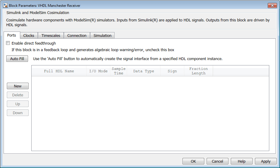
Open HDL Cosimulation Block Parameters
To open the block parameters dialog box for the HDL Cosimulation block, double-click the block icon. Simulink displays the following Block Parameters dialog box (as an example, the dialog box for the HDL Cosimulation block for use with ModelSim is shown below).

Map HDL Signals to Block Ports
The first step to configuring your HDL Verifier HDL Cosimulation block is to map signals and signal instances of your HDL design to port definitions in your HDL Cosimulation block. In addition to identifying input and output ports, you can specify a sample time for each output port. You can also specify a fixed-point data type for each output port.
The signals that you map can be at any level of the HDL design hierarchy.
To map the signals, you can perform either of the following actions:
Enter signal information manually into the Ports pane of the block parameters dialog box. This approach can be more efficient when you want to connect a small number of signals from your HDL model to Simulink.
Use the Auto Fill button to have the HDL Cosimulation block obtain signal information for you by transmitting a query to the HDL simulator. This approach can save significant effort when you want to cosimulate an HDL model that has many signals that you want to connect to your Simulink model. However, in some cases, you will need to edit the signal data returned by the query.
Note
Verify that signals used in cosimulation have read/write access. For higher performance, you want to provide access only to those signals used in cosimulation. This rule applies to all signals on the Ports, Clocks, and Simulation panes, and to all signals added in any other manner.
Specify HDL Signal/Port and Module Paths for Simulink Testbench Cosimulation. These rules are for signal/port and module path specifications in Simulink. Other specifications may work but are not explicitly or implicitly supported in this or future releases.
HDL designs generally do have hierarchy; that is the reason for this syntax. This specification does not represent a file name hierarchy.
![]() Path Specifications for Verilog Top Level
Path Specifications for Verilog Top Level
![]() Path Specifications for VHDL Top Level
Path Specifications for VHDL Top Level
Get Signal Information from HDL Simulator. The Auto Fill button lets you begin an HDL simulator query and supply a path to a component or module in an HDL model under simulation in the HDL simulator. Usually, some change of the port information is required after the query completes. You must have the HDL simulator running with the HDL module loaded for Auto Fill to work.
The following example describes the required steps.
Note
The example is based on a modified copy of the Manchester Receiver model, in which all signals were first deleted from the Ports and Clocks panes.
Open the block parameters dialog box for the HDL Cosimulation block. Click the Ports tab. The Ports pane opens (as an example, the Ports pane for the HDL Cosimulation block for use with ModelSim is shown in the illustrations below).
Tip
Delete all ports before performing Auto Fill to make sure that no unused signal remains in the Ports list at any time.
Click the Auto Fill button. The Auto Fill dialog box opens.
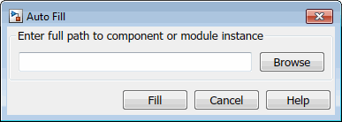
This modal dialog box requests an instance path to a component or module in your HDL model; here you enter an explicit HDL path into the edit field. The path you enter is not a file path and has nothing to do with the source files.
In this example, the Auto Fill feature obtains port data for a VHDL component called
manchester. The HDL path is specified as/top/manchester. Path specifications will vary depending on your HDL simulator, see Specify HDL Signal/Port and Module Paths for Simulink Component Cosimulation.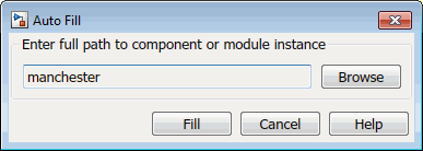
Click Fill to close the dialog box and the query is transmitted.
After the HDL simulator returns the port data, the Auto Fill feature enters it into the Ports pane, as shown in the following figure (examples shown for use with Cadence Xcelium).
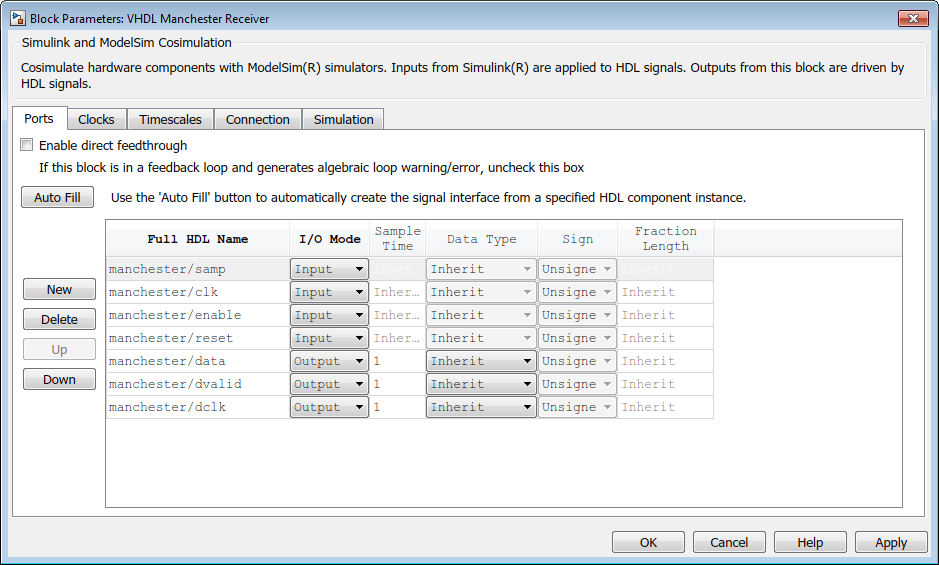
Click Apply to commit the port additions.
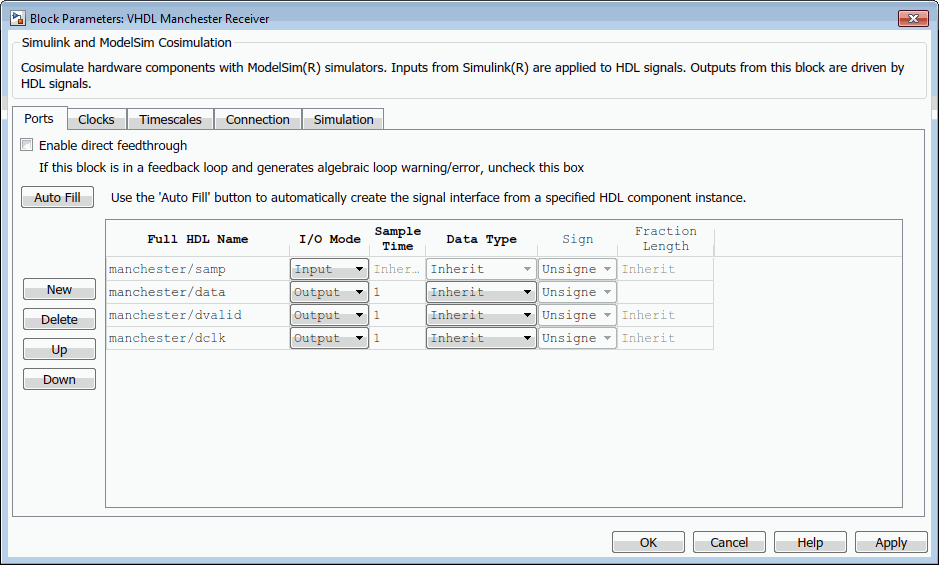
Delete unused signals from Ports pane and add Clock signal.
The preceding figure shows that the query entered clock, clock enable, and reset ports (labeled
clk,enable, andresetrespectively) into the ports list.Delete the
clk,enableandresetsignals from the Ports pane, and add theclksignal in the Clocks pane.These actions result in the signals shown in the next figures.

Auto Fill returns default values for output ports:
Sample time:
1Data type:
InheritFraction length:
Inherit
You may need to change these values as required by your model. In this example, the Sample time should be set to
10for all outputs. See “Specify Signal Data Types”.Before closing the block parameters dialog box, click Apply to commit any edits you have made.
Observe that Auto Fill returned information about all inputs and outputs for the targeted component. In many cases, this will include signals that function in the HDL simulator but cannot be connected in the Simulink model. You may delete any such entries from the list in the Ports pane if they are unwanted. You can drive the signals from Simulink; you just have to define their values by laying down Simulink blocks.
Note that Auto Fill does not return information
for internal signals. If your Simulink model needs to access
such signals, you must enter them into the Ports pane
manually. For example, in the case of the Manchester Receiver model,
you would need to add output port entries for top/manchester/sync_i, top/manchester/isum_i,
and top/manchester/qsum_i, as shown in step 8.
Xcelium and ModelSim users: Note that clk, reset, and clk_enable may be in the Clocks and Simulation panes but they don't have to be. These signals can be ports if you choose to drive them explicitly from Simulink.
Note
When you import VHDL signals using Auto Fill, the HDL simulator returns the signal names in all capitals.
Enter Signal Information Manually. To enter signal information directly in the Ports pane, perform the following steps:
In the HDL simulator, determine the signal path names for the HDL signals you plan to define in your block. For example, in the ModelSim simulator, the following wave window shows all signals are subordinate to the top-level module
manchester.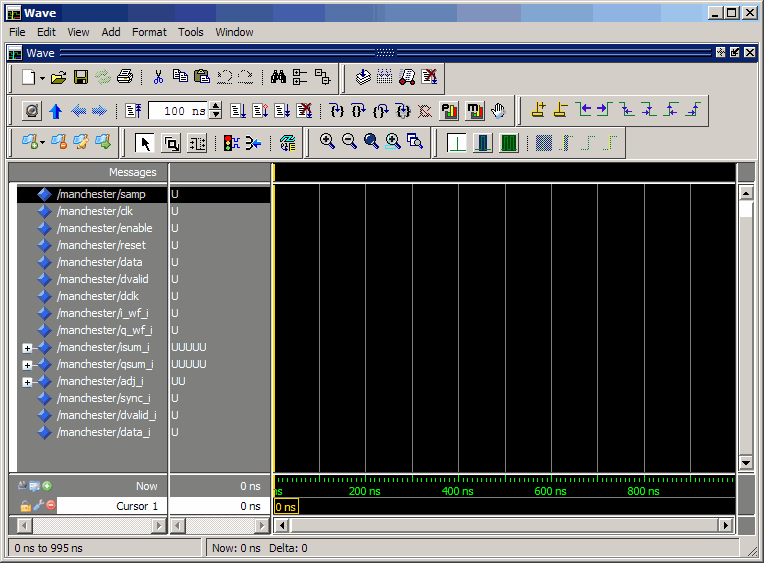
In Simulink, open the block parameters dialog box for your HDL Cosimulation block, if it is not already open.
Select the Ports pane tab. Simulink displays the following dialog box (example shown for use with Xcelium).
In this pane, you define the HDL signals of your design that you want to include in your Simulink block and set a sample time and data type for output ports. The parameters that you should specify on the Ports pane depend on the type of device the block is modeling as follows:
For a device having both inputs and outputs: specify block input ports, block output ports, output sample times and output data types.
For output ports, accept the default or enter an explicit sample time. Data types can be specified explicitly, or set to
Inherit(the default). In the default case, the output port data type is inherited either from the signal connected to the port, or derived from the HDL model.For a sink device: specify block output ports.
For a source device: specify block input ports.
Enter signal path names in the Full HDL name column by double-clicking on the existing default signal.
Use HDL simulator path name syntax (as described in Specify HDL Signal/Port and Module Paths for Simulink Testbench Cosimulation).
If you are adding signals, click New and then edit the default values. Select either
InputorOutputfrom the I/O Mode column.If you want to, set the Sample Time, Data Type, and Fraction Length parameters for signals explicitly, as discussed in the remaining steps.
When you have finished editing clock signals, click Apply to register your changes with Simulink.
The following dialog box shows port definitions for an HDL Cosimulation block. The signal path names match path names that appear in the HDL simulator wave window (Xcelium example shown).
Note
When you define an input port, make sure that only one source is set up to force input to that port. If multiple sources drive a signal, your Simulink model may produce unpredictable results.
You must specify a sample time for the output ports. Simulink uses the value that you specify, and the current settings of the Timescales pane, to calculate an actual simulation sample time.
For more information on sample times in the HDL Verifier cosimulation environment, see Simulation Timescales.
You can configure the fixed-point data type of each output port explicitly if desired, or use a default (
Inherited). In the default case, Simulink determines the data type for an output port as follows:If Simulink can determine the data type of the signal connected to the output port, it applies that data type to the output port. For example, the data type of a connected Signal Specification block is known by backpropagation. Otherwise, Simulink queries the HDL simulator to determine the data type of the signal from the HDL module.
To assign an explicit fixed-point data type to a signal, perform the following steps:
Select either
SignedorUnsignedfrom the Data Type column.If the signal has a fractional part, enter the Fraction Length.
For example, if the model has an 8-bit signal with
Signeddata type and a Fraction Length of5, the HDL Cosimulation block assigns it the data typesfix8_En5. If the model has anUnsigned16-bit signal with no fractional part (a Fraction Length of0), the HDL Cosimulation block assigns it the data typeufix16.
Before closing the dialog box, click Apply to register your edits.
Control Output Port Directly by Value of Input Port. Enabling direct feedthrough allows input port value changes to propagate to the output ports in zero time, thus eliminating the possible delay at output sample in HDL designs with pure combinational logic. Specify the option to enable direct feedthrough on the Ports pane, as shown in the following figure.

Specify Signal Data Types
The Data Type and Fraction Length parameters apply only to output signals. See Data Type and Fraction Length on the Ports pane description of the HDL Cosimulation block.
Configure Simulink and HDL Simulator Timing Relationship
You configure the timing relationship between Simulink and the HDL simulator by using the Timescales pane of the block parameters dialog box. Before setting the Timescales parameters, read Simulation Timescales to understand the supported timing modes and the issues that will determine your choice of timing mode.
You can specify either a relative or an absolute timing relationship between Simulink and the HDL simulator in the Timescales pane, as described in the HDL Cosimulation block reference.
Simulink and HDL Simulator Timing Relationship. The differences in the representation of simulation time can be reconciled in one of two ways using the HDL Verifier interface:
By defining the timing relationship manually (with Timescales pane)
When you define the relationship manually, you determine how many femtoseconds, picoseconds, nanoseconds, microseconds, milliseconds, seconds, or ticks in the HDL simulator represent 1 second in Simulink.

This quantity of HDL simulator time can be expressed in one of the following ways:
In relative terms (i.e., as some number of HDL simulator ticks). In this case, the cosimulation is said to operate in relative timing mode. The HDL Cosimulation block defaults to relative timing mode for cosimulation. For more on relative timing mode, see Relative Timing Mode.
In absolute units (such as milliseconds or nanoseconds). In this case, the cosimulation is said to operate in absolute timing mode. For more on absolute timing mode, see Absolute Timing Mode.
For more on relative and absolute time, see Simulation Timescales.
By allowing HDL Verifier to define the timescale (with Timescales pane)
When you allow the link software to define the timing relationship, it attempts to set the timescale factor between the HDL simulator and Simulink to be as close as possible to 1 second in the HDL simulator = 1 second in Simulink. If this setting is not possible, the link product attempts to set the signal rate on the Simulink model port to the lowest possible number of HDL simulator ticks.
Before you begin, verify that the HDL simulator is running. HDL Verifier software can get the resolution limit of the HDL simulator only when that simulator is running.
You can choose to have HDL Verifier calculate a timescale while you are setting the parameters on the block dialog box by clicking the Timescale option then clicking Determine Timescale Now or you can have HDL Verifier calculate the timescale when simulation begins by selecting Automatically determine timescale at start of simulation.

When you click Determine Timescale Now, HDL Verifier connects Simulink with the HDL simulator so that it can use the HDL simulator resolution to calculate the best timescale. You can accept the timescale HDL Verifier suggests or you can make changes in the port list directly. If you want to revert to the originally calculated settings, click Use Suggested Timescale. If you want to view sample times for all ports in the HDL design, select Show all ports and clocks.
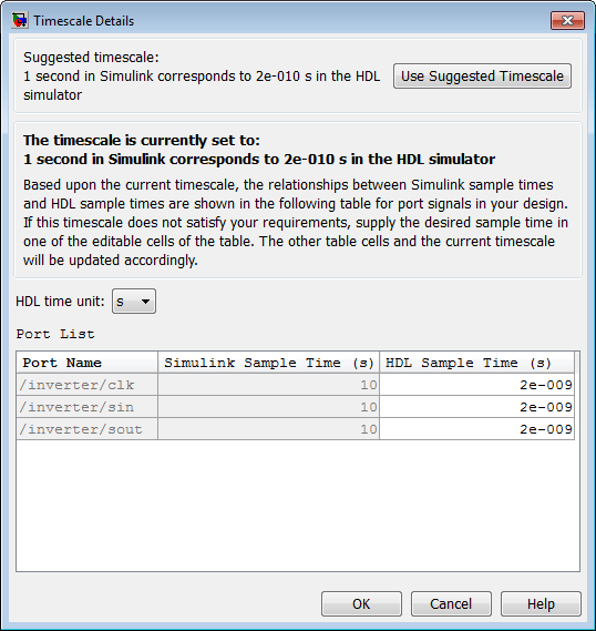
If you select Automatically determine timescale at start of simulation, you get the same dialog box when the simulation starts in Simulink. Make the same adjustments at that time, if applicable, that you would if you clicked Determine Timescale Now when you were configuring the block.
Configure Communication Link in the HDL Cosimulation Block
You must select shared memory or socket communication. See HDL Cosimulation with MATLAB or Simulink.
After you decide which type of communication, configure a block's communication link with the Connection pane of the block parameters dialog box (example shown for use with ModelSim).
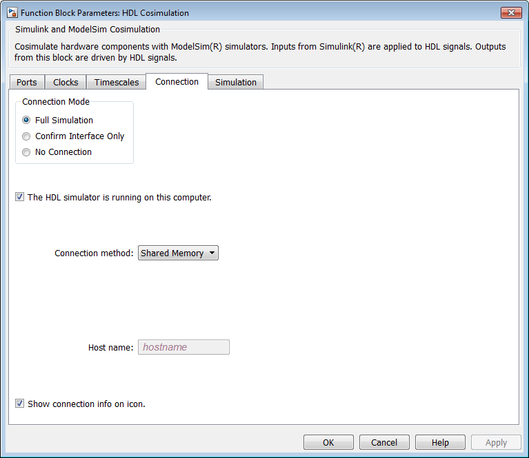
The following steps guide you through the communication configuration:
Determine whether Simulink and the HDL simulator are running on the same computer. If they are, skip to step 4.
Clear The HDL simulator is running on this computer. (This check box defaults to selected.) Because Simulink and the HDL simulator are running on different computers, HDL Verifier sets the Connection method to
Socket.Enter the host name of the computer that is running your HDL simulation (in the HDL simulator) in the Host name text field. In the Port number or service text field, specify a valid port number or service for your computer system. For information on choosing TCP/IP socket ports, see TCP/IP Socket Ports. Skip to step 5.
If the HDL simulator and Simulink are running on the same computer, decide whether you are going to use shared memory or TCP/IP sockets for the communication channel. For information on the different modes of communication, see HDL Cosimulation with MATLAB or Simulink.
If you choose TCP/IP socket communication, specify a valid port number or service for your computer system in the Port number or service text field. For information on choosing TCP/IP socket ports, see TCP/IP Socket Ports.
If you choose shared memory communication, select the Shared memory check box.
If you want to bypass the HDL simulator when you run a Simulink simulation, use the Connection Mode options to specify what type of simulation connection you want. Select one of the following options:
Full Simulation: Confirm interface and run HDL simulation (default).
Confirm Interface Only: Check HDL simulator for expected signal names, dimensions, and data types, but do not run HDL simulation.
No Connection: Do not communicate with the HDL simulator. The HDL simulator does not need to be started.
With the second and third options, HDL Verifier software does not communicate with the HDL simulator during Simulink simulation.
Click Apply.
The following example dialog box shows communication definitions for an HDL Cosimulation block. The block is configured for Simulink and the HDL simulator running on the same computer, communicating in TCP/IP socket mode over TCP/IP port 4449.

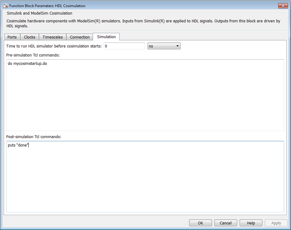
Specify Pre- and Post-Simulation Tcl Commands with HDL Cosimulation Block Parameters Dialog Box
You have the option of specifying Tcl commands to execute before and after the HDL simulator
simulates the HDL component of your Simulink model. Tcl is a programmable scripting language
supported by most HDL simulation environments. Use of Tcl can range from something as simple
as a one-line puts command to confirm that a simulation is running or as
complete as a complex script that performs an extensive simulation initialization and
startup sequence. For example, you can use the Post- simulation command
field on the Simulation Pane to instruct the HDL simulator to restart at the end of a
simulation run.
Note for ModelSim Users
After each simulation, it takes ModelSim time to update the coverage result. To prevent the potential conflict between this process and the next cosimulation session, add a short pause between each successive simulation.
You can specify the pre-simulation and post-simulation Tcl commands by entering Tcl commands in the Pre-simulation commands or Post-simulation commands text fields in the Simulation pane of the HDL Cosimulation block parameters dialog box.
To specify Tcl commands, perform the following steps:
Select the Simulation tab of the block parameters dialog box. The dialog box appears as follows (example shown for use with ModelSim).
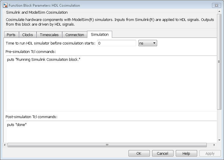
The Pre-simulation commands text box includes a
putscommand for reference purposes.Enter one or more commands in the Pre-simulation command and Post-simulation command text boxes. You can specify one Tcl command per line in the text box or enter multiple commands per line by appending each command with a semicolon (;), which is the standard Tcl concatenation operator.
Click Apply.
Programmatically Control Block Parameters
One way to control block parameters is through the HDL Cosimulation block graphical dialog box.
However, you can also control blocks by programmatically controlling
the mask parameter values and the running of simulations. Parameter
values can be read using the Simulink get_param function
and written using the Simulink set_param function.
All block parameters have attributes that indicate whether they are:
Tunable — The attributes can change during the simulation run.
Evaluated — The parameter value undergoes an evaluation to determine its actual value used by the S-Function.
The HDL Cosimulation block does not have any tunable parameters; thus, you get an error if you try to change a value while the simulation is running. However, it does have a few evaluated parameters.
You can see the list of parameters and their attributes by performing a right-mouse click on the block, selecting View Mask, and then the Parameters tab. The Variable column shows the programmatic parameter names. Alternatively, you can get the names programmatically by selecting the HDL Cosimulation block and then typing the following commands at the MATLAB prompt:
>> get_param(gcb, 'DialogParameters')
Some examples of using MATLAB to control simulations and mask parameter values follow. Usually, the commands are put into a script or function file and are called by several callback hooks available to the model developer. You can place the code in any of these suggested Simulink locations:
In the model workspace. On the Modeling tab, in the Design section, click Model Explorer. In the Model Explorer dialog box, in the Model Hierarchy pane, select Simulink Root >
model_name> Model Workspace. In the Model Workspace pane, from the Data source list. SelectModel File.In a model callback. On the Modeling tab, in the Setup section, click Model Settings > Model Properties. In the Model Properties dialog box, specify the callback function in the Callbacks tab.
In a subsystem callback. Right-mouse click on an empty subsystem and then select Properties > Callbacks. Many of the HDL Verifier demos use this technique to start the HDL simulator by placing MATLAB code in the
OpenFcncallback.In the HDL Cosimulation block callback. Right-mouse click on HDL Cosimulation block, and then select Properties > Callbacks.
Example: Scripting the Value of the Socket Number for HDL Simulator
Communication. In a regression environment, you may need to determine the socket number for the Simulink/HDL simulator connection during the simulation to avoid collisions with other
simulation runs. Use the getAvailableSocketPort function to check for an
available socket, and set both Simulink and the HDL simulator to use that socket.
This example shows code that could handle that task on a Linux® platform, using Questa™ as the HDL simulator.
p = getAvailableSocketPort();
set_param('mymodel/HDL Cosimulation',CommSharedMemory='off',CommPortNumber=num2str(p));

vsim(socketsimulink=p, tclstart={});
When using incisive, use the nclaunch function to set the socket and
start the simulator
nclaunch(socketsimulink=p, tclstart={});