Import HDL Code for HDL Cosimulation Block
Cosimulation Type—Simulink Block
Open your model, and on the Apps tab, click HDL Verifier. Then, in the Mode section, select HDL Cosimulation, and click Import HDL Files to open the Cosimulation Wizard.

Select
ModelSim,Xcelium,Vivado Simulator, orVCSfor the HDL Simulator.Select Use HDL simulator executables on the system path if that is where the files are located. The Cosimulation Wizard assumes by default that they are on the system path.
If the HDL simulator executables are not on the system path, select Use the following HDL simulator executables at the following location and specify the folder location in the text box below. If you are using Synopsys® VCS®, specify the VCS installation path, which is your
VCS_HOME.If you click Next and the Cosimulation Wizard does not find the executables, the following occurs:
You are returned to this dialog box and the Cosimulation Wizard displays an error in the status pane.
The Cosimulation Wizard switches the option to Use the following HDL simulator executables at the following location.
The Cosimulation Wizard makes the HDL simulation path field editable.
You must enter a valid path to the HDL simulator executables before you are allowed to continue.
Click Next.
HDL Files—Simulink Block

In the HDL Files pane, specify the files to be used in creating the function or block.
The Cosimulation Wizard attempts to determine the file type of each file and display the type in the File List next to the file name. If the Cosimulation Wizard cannot determine the type or displays the wrong type, you can change the type directly in the File Type column.
If possible, the Cosimulation Wizard will determine the compilation order automatically using HDL simulator provided functionality. This means you can add the files in any order.
If you are using ModelSim™, you will see compilation scripts listed as .do files (ModelSim macro file). If you are using Xcelium™, you will see compilation scripts listed as system scripts.
Click Add to select one or more file names.
Remove files by first highlighting the file name in the File List, then clicking Remove Selected File.
If you are using VCS, select the top-level module in the Top-Level column.
Click Next.
HDL Compilation—Simulink Block

In the HDL Compilation pane, you can review the generated HDL compilation commands. You may override and/or customize those commands, if you want. If you included compilation scripts instead of HDL files, this pane will show you the command to run those scripts. For VCS cosimulation, this pane shows the compilation and simulation commands.
Enter any changes to the commands in the Compilation Commands box.
Note
Do not include system shell commands; for example:
set file = a.vhd vcom $file
When control returns to the Cosimulation Wizard from executing the command, the variable no longer holds the value that was set. If you do try to include this type of command, you will see an error in the Status panel.
Click Restore default commands to go back to the generated HDL compilation commands. You are asked to confirm that you want to discard any changes.
Click Next to proceed.
Simulation Options—Simulink Block
Modelsim or Xcelium Users:
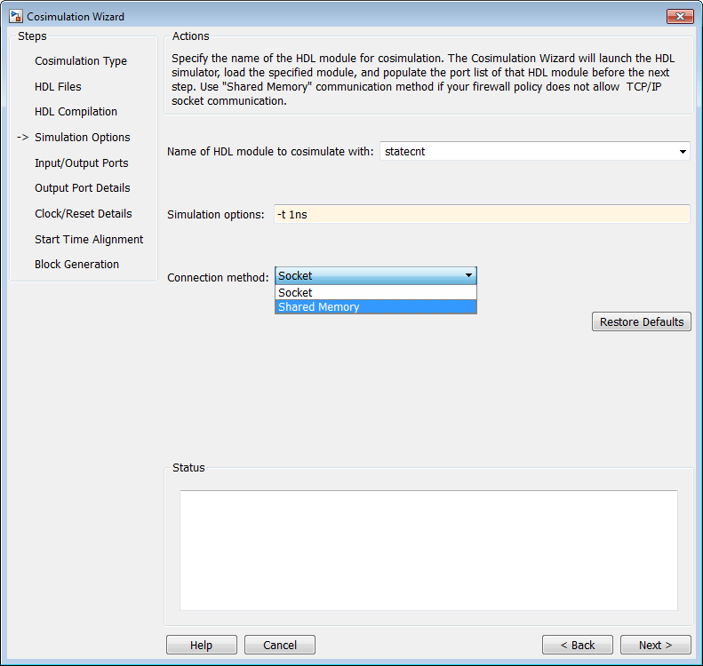
In the Simulation Options pane, provide the name of the HDL module to be used in cosimulation.
Enter the name of the module at Name of HDL module to cosimulate with.
Specify additional simulation options at Simulation options. For example, in the previous image, the options shown are:
HDL simulator resolution
Turn off optimizations that remove signals from the simulation view
Click Restore Defaults to change the options back to the default.
For Connection method, select
Shared Memoryif your firewall policy does not allow TCP/IP socket communication.Click Next to proceed to the next step. At this time in the process, the application performs the following actions in a command window:
Starts the HDL simulator.
Loads the HDL module in the HDL simulator.
Starts the HDL server, and waits to receive notice that the server has started.
Connects with the HDL server to get the port information.
Disconnects and shuts down the HDL server.
Clicking Next also generates a parameter configuration file. For more information, see Use HDL Parameters in Cosimulation.
Vivado Simulator Users:
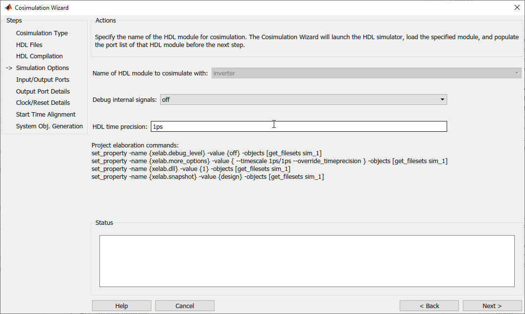
When creating a System object™ for Vivado® cosimulation, the wizard displays the name of the HDL top module.
To generate a waveform file, set Debug internal signals to
wave.
In the HDL time precision parameter you can also change the simulation time precision.
Click Next to create a shared library (dll file).
For Vivado cosimulation, this step creates a shared library.
VCS Users:
For VCS cosimulation, this pane is not available. The HDL Compilation and Simulation Options panes are combined into a single HDL Compilation and Simulation pane.
Input/Output Ports—Simulink Block

In the Simulink Ports pane, specify the type of each input and output port.
The Cosimulation Wizard attempts to determine the port types for you, but you may override any setting. For supported data types, see Supported Data Types.
For input ports, select
Input,Clock,Reset, orUnused.For output ports, select
OutputorUnused.Simulink® forces clock and reset signals in the HDL simulator through Tcl commands. You can specify clock and reset signal timing in a later step (see Clock/Reset Details—Simulink Block).
To drive your HDL clock and reset signals with Simulink signals, mark them as
Input.
Click Next to proceed to Output Port Details—Simulink Block.
Output Port Details—Simulink Block

In the Output Port Details pane, set the sample time and data type for all output ports.
Sample time default is
1, the data type default isInheritandSigned. These defaults are consistent with the way the HDL Cosimulation block mask (Ports tab) sets default settings for output ports.If you select Set all sample times and data types to 'Inherit', the ports inherit the times via back propagation (sample times are set to -1). However, back propagation may fail in some circumstances; see Backpropagation in Sample Times (Simulink).
Click Next.
Clock/Reset Details—Simulink Block

In the Clock/Reset Details pane, set the clock and reset parameters.
The time period specified here refers to time in the HDL simulator.
The clock default settings are a rising active edge and a period of 10 ns.
The reset default settings are an initial value of 1 and a duration of 8 ns.
The next screen provides a visual display of the simulation start time where you can review how the clocks and resets line up.
Click Next.
Start Time Alignment—Simulink Block

In the Start Time Alignment pane, review the current settings for clocks and resets. The purpose for this dialog box is twofold:
To make sure the rising or falling edge is set as expected (from the previous step)
Examine the start time. If it coincides with the active edge of the clock, you need to adjust the HDL simulator start time.
Examine the reset signal. If it is synchronous with the clock active edge, you may have a possible race condition.
To avoid a race condition, make sure the start time does not coincide with the active edge of any clocks. You can do this by moving the start time or by changing clock active edges in the previous step.
To make sure the start time is where you want it.
The HDL simulator start time is calculated from the clock and reset values on the previous pane. If you want, you can change the HDL simulator start time by entering a new value where you see HDL time to start cosimulation (ns). Click Update plot to see your change applied.
Click Next.
Generate Block
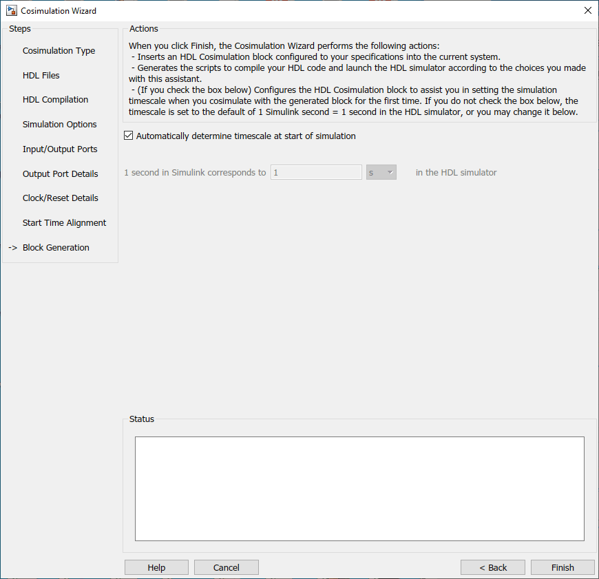
Specify if you want HDL Verifier™ to determine the timescale when you start the simulation by selecting Automatically determine timescale at start of simulation. If you prefer to determine the timescale yourself, leave this box unchecked and enter the timescale value in the text boxes below. The default is to automatically determine timescale.
For more about timescales, see Simulation Timescales.
Click Back to review or change your settings.
Click Finish to generate the HDL cosimulation block.
VCS Users:
For VCS cosimulation, the option to automatically determine the timescale is not available. You must determine the timescale and enter the timescale value in the provided text box.

Complete Simulink Model
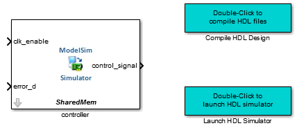
The Cosimulation Wizard tool inserts the following items to your model:
ModelSim, Xcelium, or VCS users:
An HDL Cosimulation block
A utility function to compile the HDL design
A utility function to launch the HDL simulator
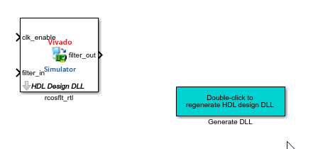
Vivado users:
An HDL Cosimulation block
A utility block to generate a DLL file
Place the block so that the inputs and outputs to the HDL Cosimulation block line up.
Connect the blocks in the destination model to the HDL Cosimulation block.
Note
If you opened the Cosimulation Wizard from the command line and not from the Simulink toolstrip, the HDL Cosimulation and the utility functions open in a new model. You first have to copy them to your model.
When you have completed the model, see Performing Cosimulation for the next steps in HDL cosimulation.