Using Simulink and Stateflow in Modeling
When using Stateflow®, Simulink® is required for inputs, outputs, and structuring. Stateflow alone can perform a variety of formula processing. When using Simulink, complex state variables can be realized through methods, such as using the Switch Case block.
Either Simulink or Stateflow can be used to model specific parts of control, however, the application of either product in the development workflow is based on the user’s understanding of the underlying algorithms and, ultimately, comes down to the organization to determine which tool is best suited for their needs. Determining whether Simulink or Stateflow should be used for design should be determined by a group of people in accordance with the task. Whether implementation in Stateflow is done by using state transitions or with flow charts should also be specified.
In most cases, Stateflow is less efficient with regards to RAM. Therefore, Simulink has an advantage in computations that use simple formulas. In addition, Simulink is more advantageous for situations where state variables are operated with simple flip-flops and the Relay block. When evaluating whether to use Simulink or Stateflow in a project, these topics should be taken into consideration:
Increasing RAM: There must always be a RAM available for visualization of Stateflow inputs, outputs and internal variables.
Equation error handling: When general computational formulas are used internally, the user designs ways to prevent overflow.
Splitting and separating functions: When performing calculations that use Simulink outside of Stateflow, there is a possibility that they may split, thus reducing readability. There are also times where readability may improve. This can be difficult to judge.
There are cases where Stateflow has more efficient code than Simulink for optimum expressions that are close to code, but most of these result in a model that is difficult to understand. If code already exists, it is more advantageous to use S-functions instead of Stateflow modeling. Stateflow can note computations where specific arrangements are specified, or computations using for-loops, more efficiently than Simulink, but in recent years it has also become convenient to use MATLAB® language for descriptions. If needed, consider using MATLAB language for modeling.
For Stateflow models, when dealing with states as described below, readability improves by describing them as state transitions:
Different output values are output for identical inputs.
Multiple states exist (as a guide, three or more).
States with meaningful names instead of just numbers.
Inside a state, initialization (first time) and differentiation during execution (after the second time) is required.
For instance, in flip-flop circuits, different values are outputted for inputs. State variables are limited to 0 and 1. However, a meaningful name cannot be added to each state simply by retaining boolean type numbers. There is also no distinction between initialization and execution within the state. Thus, only one flip-flop applies out of the four above, so Simulink is more beneficial.
In Stateflow, situations that can be represented as states are implemented as state
transitions and conditional branches that are not states are implemented as flow charts.
Truth tables are classified as a conditional branch implementation method. When
designing states as state transitions by using Stateflow, Classic should be selected as the state machine type
so that it is implemented as software into the control system’s embedded micro
controller.
HDL Coder™ is supported by Stateflow. When using HDL Coder, Mealy or Moore must be selected;
Moore mode is more appropriate when protection is required
against internal electric leaks.
Note
HDL Coder use cases are not described in these guidelines.
Simulink Functionality
This section provides information about using Simulink for modeling.
Blocks with State Variables
Blocks with state variables are primarily grouped into Simulink and discrete types.
For most of these blocks, the user can set the state attributes and initial values by using the block parameters. A conditional subsystem can have state variables, depending on the structure pattern.
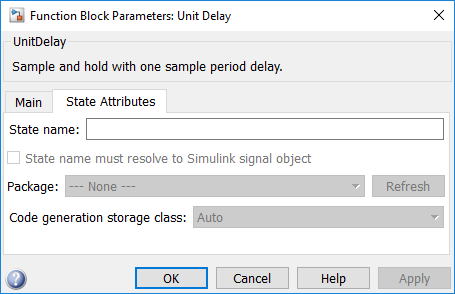
In this example, the Unit Delay block has state attributes.
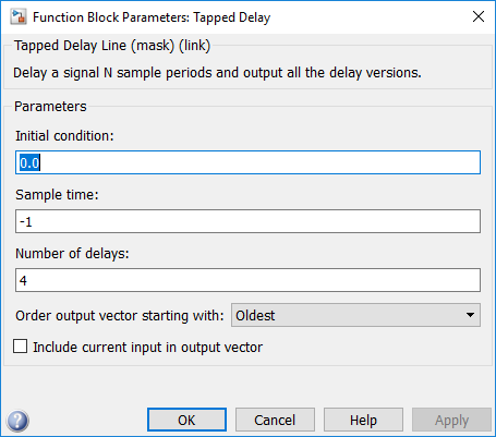
In this example, the Tapped Delay block does not have state attributes.
See guideline: jc_0640
Branch Syntax with State Variables
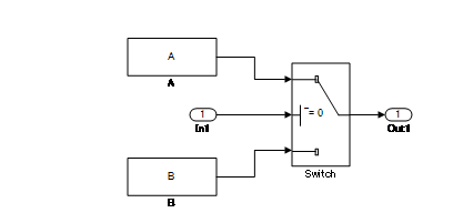
The Switch block and conditional subsystems behave differently when state variables are used.
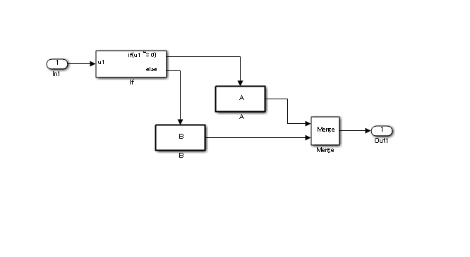
Depending on the configuration setting, when any state variable exists, the Switch block generally executes subsystem A when the condition of the control port is satisfied. If the condition is not satisfied, it executes only subsystem B without calculating subsystem A. However, when the subsystem A contains a state variable, calculation for the state variable within the subsystem A is processed even when the conditions of the control port are not satisfied.
In the conditional subsystem, subsystem A is calculated when the condition is satisfied. When it is not satisfied, subsystem B is calculated instead of subsystem A, regardless of the existence of any state variables in subsystem A.
The reset action in a recalculation can be specified by using the {Action Port} setting.
The behavior of subsystem A when using a Switch block and a conditional control flow is listed in the following tables. Familiarize yourself with these behaviors to determine which structure, the Switch block, or conditional subsystem is most suitable for the intended purpose.
This table shows the behavior of subsystem A.
| Control port condition | (in subsystem A) State variables | Switch | Conditional subsystem |
| Hold | No | Executed | Executed |
| Yes | |||
| Not hold | No | Not executed | Not executed |
| Yes | Minimally-processed *Executed calculations related to the state variables |
This table provides the initialization timing of subsystem A.
| Action Port | Initialize | |
| Switch | - | First time only |
| Conditional subsystem | Hold | First time only |
| Reset | At returned by condition |
See guidelines:
Subsystems
A subsystem is used for compiling various blocks and subsystems.
Subsystems can also be used for other purposes. Usage methods that are not functional subsystems include:
Mask display of the subsystem is used to describe the outline or display fixed form documents, such as "classified"
The open functions (callback functions in the block properties) of the subsystem is used for running several tools or displaying explanatory text separate from the model
Subsystems whose setting have changed to a mask subsystem (a subsystem that was simply set to
NoReadOrWrite) by a user with administrative rights to make a change, but other users cannot see the content.
These non-typical subsystems are outside of the scope of the guidelines and, if excluded, should be put on an exclusion list managed within the project.
See guidelines:
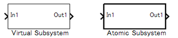
Atomic Subsystems and Virtual Subsystems. There are two types of subsystems: Virtual subsystems and Atomic subsystems. The primary difference between these subsystems is whether the subsystem is treated as a single execution unit. The virtual subsystem is the default subsystem block.
In a model, the border for a Virtual subsystem is thin as compared the border for the Atomic subsystem, which is thick and bold.
Virtual Subsystems
A block that provides a visual representation is known as a "virtual block". For example, a Mux block that compiles several signal lines, a From block that hands out the signal, and a Goto block that corresponds to a virtual block. Since the subsystem block in the default setting only constitutes a visual hierarchical structure, these blocks are considered virtual blocks. The subsystem is referred to as a virtual subsystem.
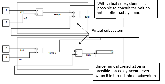
Consider a subsystem that consults an external calculation result within a subsystem, as shown in the following example. This system is calculated from these four equations.
temp1= in1 + in2
temp2= in3 + in4
out1= in1 + in2 + temp2
out2= temp1 + in3 + in4
Atomic Subsystems
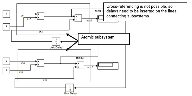
An atomic subsystem is detached from the external system and is not subject to cross-border optimization. Atomic subsystems do not use the results of the internal calculations of each subsystem. Therefore, interim output value will use a calculation result that is delayed by a session.
temp1= in1 + in2
temp2= in4 + in5
out1= in1+ in2 + in3
out2= in4+ in5 + in6
in3= temp2
in6= temp1
Atomic subsystems prohibit the direct referencing of the interim calculation results to other subsystems.
Notes on atomic subsystems:
Atomic subsystems can select C-source function settings.
As explained above, the internal section of an atomic subsystem will become encapsulated (objectified).
Depending on the relationship before and after, a static RAM section should be secured inside the subsystem for the output signal.
Atomic subsystems (including the addition of function settings) should be used with caution. Factor setting will not simply have a factor name inserted within a C code. It should be acknowledged that it is described as a mathematically independent system and the conditions under which an atomic subsystem can be used should be reviewed.
Include the relationship with the structure layer; it is necessary to determine an operation rule per project and to determine its relationship with the guideline rules.
Signal Name
Signals can be named and are referred to as signal names. When a signal is named, that signal name is displayed as a label. Updates to labels are reflected in the signal name and are also displayed.
The signal name can be propagated to a signal line via a branched signal line or port block and displayed as a signal name.
See guidelines:
Code can be generated by associating a signal name with a signal object
(Simulink object or mpt object). Type setting is
configured through the data dictionary, setting of the storage class is
optional. The recommended data type settings for these blocks include:
See guideline jc_0644: Type setting.
Vector Signals/Path Signal
Individual scalar signals that compose a vector shall have common functions, data type, and units.
Signals that do not fulfill the conditions as a vector can only be grouped as a bus signal. The Bus Selector block shall be used only with bus signal inputs. It shall not be used to extract a scalar signal from a vector signal.
The following table is an example of a vector signal.
| Types of vector | Size |
|---|---|
| Row vector | [1 n] |
| Column vector | [n 1] |
| Wheel speed subsystem | [1 wheel number] |
| Cylinder vector | [1 cylinder number] |
| Location vector based on a 2-dimensional coordination points | [1 2] |
| Location vector based on 3-dimensional coordination points | [1 3] |
The following table is an example of a bus signal.
| Bus type | Factor |
|---|---|
| Sensor bus | Force vectors |
| Location | |
| Wheel speed vector [Θlf, Θrf, Θlr, Θrr] | |
| Acceleration | |
| Pressure | |
| Controller bus | Sensor bus |
| Actuator bus | |
| Serial data bus | Circulating water temperature |
| Engine speed, front passenger seat door open |
See guidelines:
Enumerated Types
Enumerated type data refers to data that is restricted to a determined numerical value.
The type of blocks that can be used in an enumerated type in Simulink is limited.
To use an enumerated type, you must define the enumerate type by using
.m file on MATLAB. For additional information about defining enumeration data types,
see Use Enumerated Data in Simulink Models.
Stateflow Functionality
This section provides information about using Stateflow for modeling.
Operations Available for Stateflow
For additional information about the Stateflow operations, see Operations for Stateflow Data (Stateflow).
See guidelines:
Differences Between State Transition and Flow Chart
Stateflow can represent both a state transition and a flow chart.
Stateflow allows a flow chart to be designed within a state transition diagram.
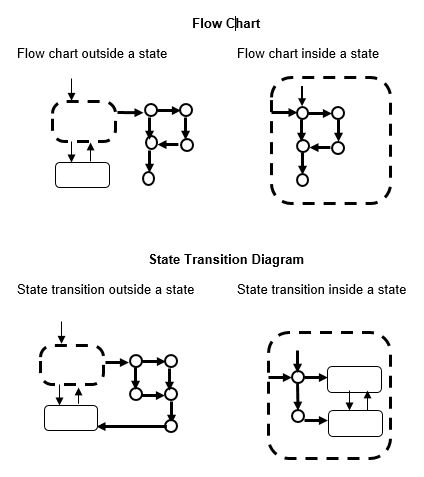
An entry action is represented as a flow chart in a state, which starts from a default transition and moves to junctions through transition lines, as illustrated below. Starting from an internal transition line allows a during action to be represented in the flow chart.
A flow chart cannot maintain its active state between updates. As a result, a flow chart always ends at a terminating junction (a connective junction that has no valid outgoing transitions).
In contrast, a state transition diagram stores its current state in memory to preserve local data and active state between updates. As a result, state transition diagrams can begin executing where they left off in the previous time step. This means that state transitions are suitable for modeling reactive or supervisory systems that depend on history.
This table defines the start and end points for a flow chart and state transition diagram.
| Start point | End point | |
| Flow chart | Default transition | All terminations from the state are connected to the connective junction. |
| State transition diagram | Default transition | Either termination should be connected to the state |
This illustration shows the difference between a general flow chart and state transition diagram
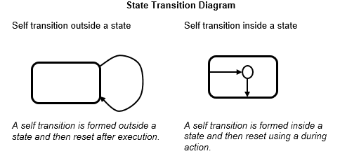
Mixture of flow charts and state transition diagrams with self-transition has more strict constraints.
See guidelines:
Backtrack
This example shows the behavior of transitions with junctions that force backtracking behavior in flow charts. The chart uses implicit ordering of outgoing transitions.
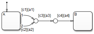
Initially, state A is active and transition conditions c1, c2, and c3 are true. Transition conditions c4 is false.
The chart root checks to see if there is a valid transition from state A.
There is a valid transition segment marked with the transition condition c1 from state A to a connective junction, therefore:
Transition condition c1 is true, so action a1 executes.
Transition condition c3 is true, so action a3 executes.
Transition condition c4 is not true and, therefore, the control flow backtracks to state A.
The chart root checks to see if there is another valid transition from state A.
There is a valid transition segment marked with the transition condition c2 from state A to a connective junction, therefore:.
Transition condition c2 is true, so action a2 executes.
Transition condition c3 is true, so action a3 executes.
Transition condition c4 is not true and, therefore, the control flow backtracks to state A.
The chart goes to sleep.
To resolve this issue, consider adding unconditional transition lines to terminating junctions. The terminating junctions allow flow to end if either c3 or c4 is not true. This design leaves state A active without executing unnecessary actions.

See guidelines:
Flow Chart Outside the State
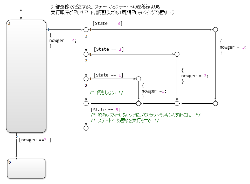
A flow chart associated with a state can be written inside or outside of the state; however, be attentive to the execution order and backtracking.
The following flow chart, which evaluates transition from a to b after executing the flow chart outside the state, appears to execute the transition within the same period as that of a newer calculation. However, the transition line to b is not evaluated if the termination point is reached by calculating the transition outside the state. This is a state transition diagram which always stays at a.
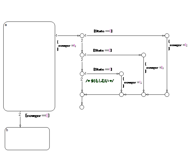
Done correctly, as shown below, the transition condition is not positioned at the termination of the external flow chart, allowing the transition line from a to b to be evaluated after the flow chart is executed. This enables the external flow chart to execute before the transition, and to be evaluated using the most recent value at the instant of the transition. Note that this chart contains a dead path where the transition condition will never hold, which can cause an error when the specification is changed in the future. Use this chart structure with caution.
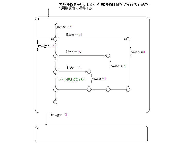
In contrast, the following flow chart is inside a state, which means that the internal flow chart is always calculated when executing state a and can be described as an easily comprehensible structure without dead paths. However, it should be noted that, as a performance characteristic, when state a is executed, the transition from a to b is evaluated in the cycle following that in which the internal flow chart is calculated. Due to this characteristic, the timing of the execution of calculations and transitions for the external flow chart may be off. Use with caution.
See guidelines:
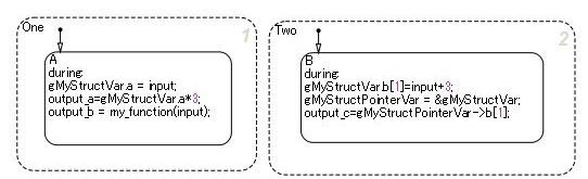
Pointer Variables
This code sample is from model sf_custom. To open the
model, enter the following on the MATLAB command
line:
openExample('sf_custom')sf_custom, click Open
my_header.h.
#include "tmwtypes.h"

extern real_T my_function(real_T x);

/* Definition of custom type */
typedef struct {
	real_T a;
	int8_T b[10];
}MyStruct;

/* External declaration of a global struct variable */
extern MyStruct gMyStructVar;
extern MyStruct *gMyStructPointerVar;
sf_custom, click Open
my_function.c.#include "my_header.h"
#include <stdio.h>
/* Definition of global struct var */
MyStruct gMyStructVar;
MyStruct *gMyStructPointerVar=NULL;
real_T my_function(real_T x)
{
real_T y;
y=2*x;
return(y);
}
gMyStructVar is not defined in Stateflow. Typically, functions of my_function are called
from C source for use in Stateflow. However, direct reference to global variables exposed by the C
source is also available from Stateflow.
Initialization
This section provides information about using initialization values.
Initial Value Setting in Initialization
When a signal needs to be initialized, the initial values shall be set correctly.
When initial values are set inside a block, use an initial value list that includes annotations so you can visually confirm the initial values input.
Cases that require initial values include:
When state variables are defined AND blocks that have state variables are used.
Use the internal block settings.
Use the external input values.
When state variables are defined AND initial values are enabled for a block when a specific configuration is performed.
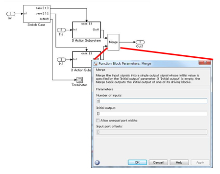
Set initial values in Merge blocks.
Use signals registered in the data dictionary.
When signal settings (with RAM) have been defined that can be referenced from the outside.
Use signals registered in the data dictionary.
Initial Values of Signals Registered in the Data Dictionary
Set initial values for signals registered in the data dictionary.
Discrete block groups, such as Unit Delay and Data Store Memory, have state variables.
In the case of automatic code generation, the signal name, type, and initial value can be set for state variables by matching it to the signal in the data dictionary (associated with Simulink signal objects). When using a signal defined in the data dictionary for a state variable, the respective initial values should conform to the same value.
When using a signal defined in the data dictionary for a state variable
For discrete blocks, such as Unit Delay and Data Store Memory, settings are performed not when using signals defined in the data dictionary for the block output line, but for the state variables inside the block. Even when the signal name of the data dictionary is assigned to the signal line, RAM is reserved in duplicate, which is a waste of RAM.
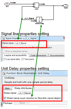
Example — Correct
Signal is defined for the state variables inside the block. The signal name is defined and block parameter State name must resolve to Simulink signal object is selected.
Example — Incorrect
Signal is defined for the output signal of the block that has state variables. The signal name is defined and block parameter State name must resolve to Simulink signal object is not selected.

Signal objects that are defined in the Workspace can be automatically
associated with signal objects and signal names of the same name by using
disableimplicitsignalresolution(modelname). However,
for state variables inside the block, they are associated with the state
variables inside the block and the signal name of the same name. If a globally
set signal is associated with two variables at the same time, it is better to
perform settings so that the state variables inside a block and the signal label
on the signal line have different names, otherwise the model cannot be
simulated.
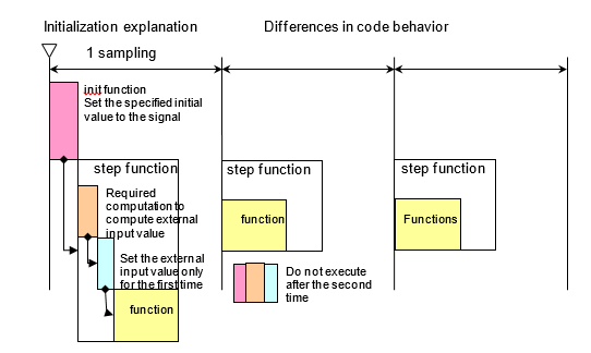
Block Whose External Input Value Is the Initial Value
When setting the initial value during initialization, the
init function is called to set the signal to either the
value inside of the block or to the initial value that is defined in the data
dictionary. Next, the step function (the data flow executive function) is
executed. Here, the external input value is set as the initial value. When
modeling, be attentive to the execution functions and execution timing for
initialization. This is demonstrated in the following image.

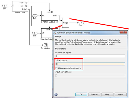
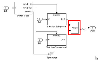
Initial Value Settings in a System Configuration That Would Enable Initialization Parameters
There are system configurations where, depending on their settings, initialization parameters are enabled for combinations of conditional subsystems and Merge blocks. When initial values are required in these combinations, either of the following modeling methods is performed:
The exception is when there are successive blocks with initial values and the settings for each block are not needed to clearly show the signal’s initial value.
Example — Correct
Initial value set in the Merge block.
Example — Correct
Initial value set in mpt object.
Example — Incorrect
Despite the requirement for an initial value setting, it is not shown anywhere.