Control Data Types of Signals
To control the data type of a signal in a Simulink® model, you specify a data type for the corresponding block output.
You can also introduce a new signal of a specific data type into a model in any of the following ways:
Load signal data of the desired type from the MATLAB® workspace into your model via a root-level Inport block or a From Workspace block.
Create a Constant block in your model and set its parameter to the desired type.
Use a Data Type Conversion block to convert a signal to the desired data type.
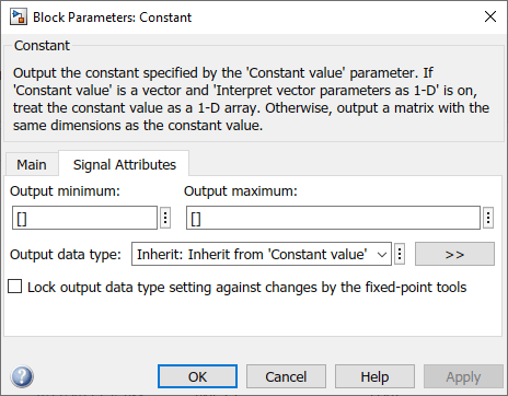
Simulink blocks determine the data type of their outputs by default. Many blocks allow you to override the default type and explicitly specify an output data type, using a block parameter that is typically named Output data type. For example, the Output data type parameter appears on the Signal Attributes pane of the Constant block dialog box.
See the following topics for more information:
| For Information About... | See... |
|---|---|
Valid data type values that you can specify | |
An assistant that helps you specify valid data type values | |
Specifying valid data type values for multiple blocks simultaneously |
Entering Valid Data Type Values
In general, you can specify the output data type as any of the following:
A rule that inherits a data type (see Data Type Inheritance Rules)
The name of a built-in data type (see Built-In Data Types)
An expression that evaluates to a data type (see Data Type Expressions)
Valid data type values vary among blocks. You can use the drop-down menu associated with a block data type parameter to view the data types that a particular block supports. For example, the Data type drop-down menu on the Data Store Memory block dialog box lists the data types that it supports, as shown here.
For more information about the data types that a specific block supports, see the documentation for the block in the Simulink documentation.
Data Type Inheritance Rules
Blocks can inherit data types from a variety of sources, including signals to which they are connected and particular block parameters. You can specify the value of a data type parameter as a rule that determines how the output signal inherits its data type. To view the inheritance rules that a block supports, use the data type drop-down menu on the block dialog box. The following table lists typical rules that you can select.
| Inheritance Rule | Description |
|---|---|
Inherit: Inherit via back propagation | Simulink automatically determines the output data type of the block during data type propagation (see Data Type Propagation). In this case, the block uses the data type of a downstream block or signal object. |
Inherit: Same as input | The block uses the data type of its sole input signal for its output signal. |
Inherit: Same as first input | The block uses the data type of its first input signal for its output signal. |
Inherit: Same as second input | The block uses the data type of its second input signal for its output signal. |
Inherit: Inherit via internal rule | The block uses an internal rule to determine its output data type. The internal rule chooses a data type that optimizes numerical accuracy, performance, and generated code size, while taking into account the properties of the embedded target hardware. It is not always possible for the software to optimize efficiency and numerical accuracy at the same time. |
When you apply inherited data types to a signal, Simulink determines the specific data type of the signal only after you update the block diagram.
To display this specific data type on the block diagram, see Port Data Types.
To inspect this specific data type for multiple signals in a searchable, sortable table, use the Model Data Editor (on the Modeling tab, click Model Data Editor). The right side of the Data Type column shows the specific data type for each signal. For more information, see Model Data Editor.
Built-In Data Types
You can specify the value of a data type parameter as the name of a built-in data type, for
example, single or boolean. To view the built-in
data types that a block supports, use the data type drop-down menu on the block dialog
box. See Data Types Supported by Simulink for a list of all built-in data types that are
supported.
Data Type Expressions
You can specify the value of a data type parameter as an expression that evaluates to a numeric data type object. Simply enter the expression in the data type field on the block dialog box. In general, enter one of these expressions:
fixdtCommandSpecify the value of a data type parameter as a command that invokes the
fixdtfunction. This function allows you to create aSimulink.NumericTypeobject that describes a fixed-point or floating-point data type.Data Type Object Name
Specify the value of a data type parameter as the name of an object that represents a data type.
Simulink.NumericType,Simulink.AliasType,Simulink.ValueType, andSimulink.BusElementobjects simplify the task of making model-wide changes to output data types.Simulink.AliasTypeobjects allow you to use custom aliases for data types.Simulink.ValueTypeandSimulink.BusElementobjects allow you to specify the data type and other parameters, such as the unit, minimum value, and maximum value.
Use the Model Data Editor for Batch Editing
Using the Model Data Editor, you can assign the same data type to multiple signals simultaneously. You can use this technique to design the interface of your model by configuring data types and other attributes of multiple Inport and Outport blocks at once (see Configure Data Interfaces). You can also finely control the data types of arbitrary signals in your block algorithm.
For example, the slexAircraftExample model contains numerous
Gain blocks. Suppose you want to specify the output data type of
the three Gain blocks at the root level of the model as single.
You can achieve this task as follows:
Open the
slexAircraftExamplemodel.open_system('slexAircraftExample')In the Model Data Editor (on the Modeling tab, click Model Data Editor), inspect the Signals tab.
Next to the Filter contents box, toggle the Filter using selection button.
At the top level of the model, select the signal lines that represent the outputs of the three Gain blocks (labeled
Zw,Mw, andMq). The Model Data Editor shows three rows that correspond to the three signals.In the Model Data Editor, select all three signals (rows). For example, you can press Ctrl+A or hold Shift while clicking the top and bottom rows in the Source column.
For any of the three signals, click the cell in the Data Type column. From the drop-down list, select
single. The Model Data Editor applies this selection to all of the selected rows.
To convert a model to a strict single precision design, see Validate a Floating-Point Embedded Model.
Share a Data Type Between Separate Algorithms, Data Paths, Models, and Bus Elements
In some cases, you cannot rely on data type inheritance (see Data Type Inheritance Rules) to establish equivalence between the data
types of different data items (such as signal lines in parallel data paths or bus
elements in a Simulink.Bus object). Instead, you
can create a Simulink.NumericType or Simulink.AliasType object in a workspace or data
dictionary.
Create a Simulink.NumericType object if you
do not want to rename the shared data type by creating an alias. Set
the IsAlias property to false (the
default).
This example shows how to use a Simulink.NumericType object
to share an output data type between two lookup table blocks in the
same model.
Open the Model Fault-Tolerant Fuel Control System example model
sldemo_fuelsys.openExample('simulink_automotive/ModelingAFaultTolerantFuelControlSystemExample') sldemo_fuelsysThe model creates
Simulink.NumericTypeobjects in the base workspace. One of the objects is nameds16En15.At the command prompt, inspect the properties of
s16En15.s16En15
s16En15 =

  NumericType with properties:

    DataTypeMode: 'Single'
         IsAlias: 0
       DataScope: 'Auto'
      HeaderFile: ''
     Description: ''
This object represents the built-in Simulink data type
single.In the model, navigate into the
fuel_rate_control/airflow_calcsubsystem.On the Modeling tab, click Model Data Editor. In the Model Data Editor, inspect the Signals tab.
In the model, click the output signal of the Pumping Constant block. The Model Data Editor Data Type column shows that the signal data type is set to
s16En15.Click the output signal of the Ramp Rate Ki block. The output data type of this block is also set to
s16En15.Update the block diagram and, if necessary, expand the width of the Data Type column. The right side of the column shows that the two lookup table blocks use the data type
single.At the command prompt, configure
s16En15to represent the data typedouble.s16En15.DataTypeMode = 'Double';Update the block diagram.
The output signals of the two lookup table blocks now use the data type
double. Due to data type inheritance, other signals, such ase0ande1, acquire the same data type.
Alternatively, to establish data type equivalence between algorithms or data paths in the same model, you can use blocks such as Data Type Propagation and Data Type Conversion Inherited. When you use these blocks, you do not need to create and permanently store a data type object. However, you cannot use the blocks to share a data type between signals in different models unless the models are in the same model reference hierarchy.
Reuse Custom C Data Types for Signal Data
In a model, you can create signals that conform to custom C data types, such as structures, that your existing C code defines. Use these signals to:
Replace existing C code with a Simulink model.
Integrate C code for simulation in Simulink (for example, by using the Legacy Code Tool).
Prepare to generate code (Simulink Coder™) that you can integrate with existing code.
Use these techniques to match your custom data types:
For a structure type, create a
Simulink.Busobject. Use the object as the data type for buses. See Define Bus Properties for Reuse.For an enumeration, create an enumeration class and use it as the data type for signals. See Use Enumerated Data in Simulink Models.
To match a
typedefstatement that represents an alias of a primitive, numeric data type, use aSimulink.AliasTypeobject as the data type for signals. SeeSimulink.AliasType.
To create these classes and objects, you can use the function Simulink.importExternalCTypes.
If a MATLAB Function block or Stateflow® chart in your model uses an imported enumeration or structure type,
configure the model configuration parameters to include
(#include) the type definition from your external header file.
See Control Imported Bus and Enumeration Type Definitions (for a
MATLAB Function block) and Access Custom Code Variables and Functions in Stateflow Charts (Stateflow) and Integrate Custom Structures in Stateflow Charts (Stateflow) (for a chart).
Determine Data Type of Signal That Uses Inherited Setting
When a signal uses an inherited data type setting such as Inherit: Inherit via
internal rule (the default setting for most blocks), to determine
the meaningful data type that the signal uses for simulation, update the block
diagram and then use one or both of these techniques:
In the Simulink Editor, on the Debug tab, select Information Overlays and navigate to the ports section. Select the port data type you want to display. The data types appear on the block diagram next to each signal. For more information, see Port Data Types.
Inspect the right side of the Data Type column in the Model Data Editor (on the Modeling tab, click Model Data Editor). For more information, see Model Data Editor.
Using these techniques to inspect data types helps you to:
Design the data type strategy for a model on a high level.
Debug numerical issues due to quantization and overflows.
Make a model more easily understood when sharing it.
For more information, see Port Data Types.
Data Types Remain double Despite Changing Settings
If many of the data items (signals, parameters, and states)
in your model continue to use the data type double after
you configure block parameters such as Output data type,
confirm that the model is not configured to override data types. See Control Data Type Override.
See Also
Simulink.AliasType | Simulink.NumericType | Simulink.Bus