Create App for Simulink Model
This example shows how to use App Designer to interactively develop an app that runs and visualizes the results of a bouncing ball simulation without writing any code. In this example, you build the app using these steps:
Create a new blank app for a Simulink® model, and associate the app with the bouncing ball model.
Design the app by adding UI components and connecting them to the associated model elements. For example, use UI components to start and stop the simulation, tune model variables, and visualize simulation signals.
Run the app and interact with the simulation.
Open the example to make the bouncing ball model available in your current folder.
openExample("simulink/CreateSimpleAppForSimulinkModelExample")Alternatively, you can walk through the example using an interactive tutorial. Open the App Designer start page. In the Simulink Apps section, click Show examples, and then click Simulink App Tutorial.
Create App with Associated Model
Create a new blank app for a Simulink model. You can do this in multiple ways, depending on where you are working:
From Simulink — Open the
bouncingBall.slxmodel in Simulink. In the Apps tab, select Design App > Create App for Model.From App Designer — Open App Designer. On the App Designer start page, in the Simulink Apps section, click Blank App for Simulink Model. Select the
bouncingBall.slxmodel in the Associate Simulink Model dialog box.
In both cases, a new app opens in App Designer and the bouncing ball model is automatically associated with the app.
Design App
App Designer has a set of Simulink UI components that control common simulation tasks, such as starting and stopping the simulation and showing the simulation progress. These Simulink components are automatically connected with the associated model. You can access these components in the Component Library, in the Simulink section.

You can also use general UI components and manually connect the components to elements of your model.
Start and Stop Simulation
Start, stop, and pause the simulation from your app by using a Simulation Controls component. Drag the component from the Simulink section of the Component Library onto the canvas.
App Designer automatically configures the UI component to interface with the model associated with the app.

Tune Model Variables
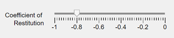
Provide a way to tune a model variable from the app while the simulation is running by connecting a UI component to the variable. For this example, create a slider to tune the coefficient of restitution variable, which represents the elasticity of the bouncing ball.
First, drag a Slider component from the Component Library onto the canvas. Configure the slider limits and value to align with the variable. Select the slider and modify properties in the Component Browser:
Specify
Limitsas[-1 0].Specify
Valueas-0.8.
Then, connect the slider to the model variable by creating a binding. Right-click the slider and select Add Binding. The Simulink model opens in connect mode. Click the Coefficient of Restitution block and select the model variable from the Connect options.

When you add a binding, the slider is connected to the variable. When the app is running, if the value of the slider changes, the value of the model variable updates to match.
Finally, update the slider label to describe the variable it is connected to.
Visualize Simulation Signals
Visualize signals in the app while the simulation is running by using a time scope UI component. For this example, visualize the position and velocity of the bouncing ball.
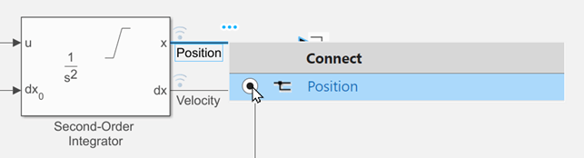
First, drag a Time Scope component from Simulink section of the Component Library onto the canvas.
Then, connect the time scope to the Position signal by creating a binding. Right-click the time scope and select Add Binding. The Simulink model opens in connect mode. Click the Position signal and select the model variable from the Connect options.
Follow the same steps to connect the time scope to the Velocity signal by creating a binding.
App Designer apps support binding only to logged signals. For more information about how to log signals, see Save Signal Data Using Signal Logging.
You can view the bindings for a component by selecting the component and opening the Bindings pane in the Component Browser. You can also use this pane to delete or modify bindings.

After you create the bindings, configure the time scope display to provide information about the plotted signals. Select the time scope and modify properties in the Component Browser:
Select
LegendVisible.Specify
TitleasPosition and Velocity of Bouncing Ball.

Run App
To run the app, click Run in the App Designer toolstrip. To start the simulation once the app is running, click Run on the simulation controls. Tune the coefficient of restitution using the slider and explore the result using the time scope.

See Also
uitimescope | uislider | App
Designer