Interleaving
Block Interleaving
Block Interleaving Features
A block interleaver accepts a set of symbols and rearranges them, without repeating or omitting any of the symbols in the set. The number of symbols in each set is fixed for a given interleaver. The interleaver's operation on a set of symbols is independent of its operation on all other sets of symbols.
An interleaver permutes symbols according to a mapping. A corresponding deinterleaver uses the inverse mapping to restore the original sequence of symbols. Interleaving and deinterleaving can be useful for reducing errors caused by burst errors in a communication system.
Each interleaver function has a corresponding deinterleaver function. In typical usage of the interleaver/deinterleaver pairs, the inputs of the deinterleaver match those of the interleaver, except for the data being rearranged.
A block interleaver accepts a set of symbols and rearranges them, without repeating or omitting any of the symbols in the set. The number of symbols in each set is fixed for a given interleaver.
The set of block interleavers in this toolbox includes a general block interleaver as well as several special cases. Each special-case interleaver function uses the same computational code that the general block interleaver function uses, but provides a syntax that is more suitable for the special case. The interleaver functions are described below.
| Type of Interleaver | Interleaver Function | Description |
|---|---|---|
| General block interleaver | intrlv | Uses the permutation table given explicitly as an input argument. |
| Algebraic interleaver | algintrlv | Derives a permutation table algebraically, using the Takeshita-Costello or Welch-Costas method. These methods are described in [4]. |
| Helical scan interleaver | helscanintrlv | Fills a matrix with data row by row and then sends the matrix contents to the output in a helical fashion. |
| Matrix interleaver | matintrlv | Fills a matrix with data elements row by row and then sends the matrix contents to the output column by column. |
| Random interleaver | randintrlv | Chooses a permutation table randomly using the initial state input that you provide. |
Types of Block Interleavers. The set of block interleavers in this library includes a general interleaver/deinterleaver pair as well as several special cases. Each special-case block uses the same computational code that its more general counterpart uses, but provides an interface that is more suitable for the special case.
The Matrix Interleaver block
accomplishes block interleaving by filling a matrix with the input symbols
row by row and then sending the matrix contents to the output port column by
column. For example, if the interleaver uses a 2-by-3 matrix to do its
internal computations, then for an input of
[1 2 3 4 5 6], the block
produces an output of
[1 4 2 5 3 6].
The Random Interleaver block chooses a permutation table randomly using the Initial seed parameter that you provide in the block mask. By using the same Initial seed value in the corresponding Random Deinterleaver block, you can restore the permuted symbols to their original ordering.
The Algebraic Interleaver block uses a permutation table that is algebraically derived. It supports Takeshita-Costello interleavers and Welch-Costas interleavers. These interleavers are described in [4].
Improve Error Rate Using Block Interleaving in MATLAB
The following example illustrates how an interleaver improves the error rate in a communication system whose channel produces a burst of errors. A random interleaver rearranges the bits of numerous codewords before two adjacent codewords are each corrupted by three errors.
Three errors exceed the error-correction capability of the Hamming code. However, the example shows that when the Hamming code is combined with an interleaver, this system is able to recover the original message despite the 6-bit burst of errors. The improvement in performance occurs because the interleaving effectively spreads the errors among different codewords so that the number of errors per codeword is within the error-correction capability of the code.
st1 = 27221; st2 = 4831; % States for random number generator
n = 7; k = 4; % Parameters for Hamming code
msg = randi([0 1],k*500,1); % Data to encode
code = encode(msg,n,k,'hamming/binary'); % Encoded data
% Create a burst error that will corrupt two adjacent codewords.
errors = zeros(size(code)); errors(n-2:n+3) = [1 1 1 1 1 1];

% With Interleaving
%------------------
inter = randintrlv(code,st2); % Interleave.
inter_err = bitxor(inter,errors); % Include burst error.
deinter = randdeintrlv(inter_err,st2); % Deinterleave.
decoded = decode(deinter,n,k,'hamming/binary'); % Decode.
disp('Number of errors and error rate, with interleaving:');
[number_with,rate_with] = biterr(msg,decoded) % Error statistics

% Without Interleaving
%---------------------
code_err = bitxor(code,errors); % Include burst error.
decoded = decode(code_err,n,k,'hamming/binary'); % Decode.
disp('Number of errors and error rate, without interleaving:');
[number_without,rate_without] = biterr(msg,decoded) % Error statistics
The output from the example follows.
Number of errors and error rate, with interleaving:

number_with =

     0


rate_with =

     0

Number of errors and error rate, without interleaving:

number_without =

     4


rate_without =

    0.0020
Improve Error Rate Using Block Interleaving in Simulink
The following example shows how to use an interleaver to improve the error rate when the channel produces bursts of errors.
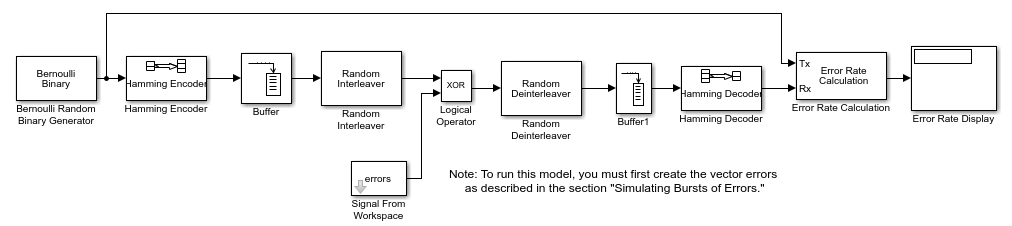
Before running the model, you must create a binary vector that simulates bursts of errors, as described in Improve Error Rate Using Block Interleaving in Simulink. The Signal From Workspace block imports this vector from the MATLAB workspace into the model, where the Logical Operator block performs an XOR of the vector with the signal.
To build the model, gather and configure these blocks:
Check the box next to Frame-based outputs.
Set Samples per frame to
4.
Hamming Encoder, with default parameter settings.
Buffer, with these updates to parameter settings:
Set Output buffer size (per channel) to
84.
Set Number of elements to
84.
Logical Operator (Simulink), with these updates to parameter settings:
Set Operator to
XOR.
Signal From Workspace, with these updates to parameter settings:
Set Signal to
errors.Set Sample time to
4/7.Set Samples per frame to
84.
Random Deinterleaver, with these updates to parameter settings:
Set Number of elements to
84.
Buffer, with these updates to parameter settings:
Set Output buffer size (per channel) to
7.
Hamming Decoder, with default parameter settings.
Error Rate Calculation, with these updates to parameter settings:
Set Receive delay to
(4/7)*84.Set Computation delay to
100.Set Output data to
Port.
Display (Simulink), with default parameter settings.
On the Simulation tab, in the
Simulate section, set Stop
time to length(errors). The
Simulate section appears on multiple tabs.
Creating the Vector of Errors. Before running the model, use the following code to create a binary vector in the MATLAB workspace. The model uses this vector to simulate bursts of errors. The vector contains blocks of three 1s, representing bursts of errors, at random intervals. The distance between two consecutive blocks of 1s is a random integer between 1 and 80.
errors=zeros(1,10^4);
n=1;
while n<10^4-80;
n=n+floor(79*rand(1))+3;
errors(n:n+2)=[1 1 1];
end
To determine the ratio of the number of 1s to the total number of symbols
in the vector errors enter
sum(errors)/length(errors)
Your answer should be approximately 3/43, or .0698, since after each sequence of three 1s, the expected distance to the next sequence of 1s is 40. Consequently, you expect to see three 1s in 43 terms of the sequence. If there were no error correction in the model, the bit error rate would be approximately .0698.
When you run a simulation with the model, the error rate is approximately .019, which shows the improvement due to error correction and interleaving. You can see the effect of interleaving by deleting the Random Interleaver and Random Deinterleaver blocks from the model, connecting the lines, and running another simulation. The bit error rate is higher without interleaving because the Hamming code can only correct one error in each codeword.
Convolutional Interleaving
Convolutional Interleaving Features
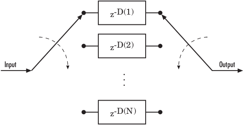
A convolutional interleaver consists of a set of shift registers, each with a fixed delay. In a typical convolutional interleaver, the delays are nonnegative integer multiples of a fixed integer (although a general multiplexed interleaver allows unrestricted delay values). Each new symbol from an input vector feeds into the next shift register and the oldest symbol in that register becomes part of the output vector. A convolutional interleaver has memory; that is, its operation depends not only on current symbols but also on previous symbols.
The total delay due to a convolutional interleaver and deinterleaver pair is N × slope × (N – 1).
N is the number of registers
slope is the register length step
This diagram shows the structure of a general convolutional interleaver comprised of a set of shift registers, each having a specified delay shown as D(1), D(2),..., D(N), and a commutator to switch input and output symbols through registers. The kth shift register holds D(k) symbols, where k = 1, 2, 3, … N. The kth shift register has a delay value of ((k–1) × slope). With each new input symbol, the commutator switches to a new register and shifts in the new symbol while shifting out the oldest symbol in that register. When the commutator reaches the Nth register, upon the next new input, the commutator returns to the first register.
Communications Toolbox™ implements convolutional interleaving functionality using Simulink® blocks, System objects, and MATLAB® functions. The convolutional interleavers in this toolbox have input arguments that indicate the number of shift registers and the delay for each shift register.
The set of convolutional interleavers in this product includes a general interleaver/deinterleaver pair as well as several special cases. Each special-case function uses the same computational code that its more general counterpart uses, but provides a syntax that is more suitable for the special case. The special cases are described below.
| Type of Interleaver | Interleaving Function | Description |
|---|---|---|
| General multiplexed interleaver | muxintrlv | Allows unrestricted delay values for the set of shift registers. |
| Convolutional interleaver | convintrlv | The delay values for the set of shift registers are nonnegative integer multiples of a fixed integer that you specify. |
| Helical interleaver | helintrlv | Fills an array with input symbols in a helical fashion and empties the array row by row. |
The helscanintrlv function and
the helintrlv function both use a
helical array for internal computations. However, the two functions have some
important differences:
helintrlvuses an unlimited-row array, arranges input symbols in the array along columns, outputs some symbols that are not from the current input, and leaves some input symbols in the array without placing them in the output.helscanintrlvuses a fixed-size matrix, arranges input symbols in the array across rows, and outputs all the input symbols without using any default values or values from a previous call.
Types of Convolutional Interleavers. The set of convolutional interleavers in this library includes a general interleaver/deinterleaver pair as well as several special cases. Each special-case block uses the same computational code that its more general counterpart uses, but provides an interface that is more suitable for the special case.
The most general block in this library is the General Multiplexed Interleaver block, which allows arbitrary delay values for the set of shift registers. To implement the preceding schematic using this block, use an Interleaver delay parameter of [D(1); D(2); ...; D(N)].
More specific is the Convolutional Interleaver block, in which the delay value for the kth shift register is (k-1) times the block's Register length step parameter. The number of shift registers in this block is the value of the Rows of shift registers parameter.
Finally, the Helical Interleaver block supports a special case of convolutional interleaving that fills an array with symbols in a helical fashion and empties the array row by row. To configure this interleaver, use the Number of columns of helical array parameter to set the width of the array, and use the Group size and Helical array step size parameters to determine how symbols are placed in the array. See the reference page for the Helical Interleaver block for more details and an example.
Delays of Convolutional Interleavers
After a sequence of symbols passes through a convolutional interleaver and a
corresponding convolutional deinterleaver, the restored sequence lags behind the
original sequence. The delay, measured in symbols, between the original and
restored sequences is indicated in the table below. The variable names in the
second column (delay, nrows,
slope, col, ngrp,
and stp) refer to the inputs named on each function's
reference page.
Delays of Interleaver/Deinterleaver Pairs
| Interleaver/Deinterleaver Pair | Delay Between Original and Restored Sequences |
|---|---|
muxintrlv,
muxdeintrlv | length(delay)*max(delay) |
convintrlv,
convdeintrlv | nrows*(nrows-1)*slope |
helintrlv,
heldeintrlv | col*ngrp*ceil(stp*(col-1)/ngrp) |
Delays of Convolutional Interleavers. After a sequence of symbols passes through a convolutional interleaver and a corresponding convolutional deinterleaver, the restored sequence lags behind the original sequence. The delay, measured in symbols, between the original and restored sequences is
Number of shift registers × Maximum delay among all shift registers
for the most general multiplexed interleaver. If your model incurs an additional delay between the interleaver output and the deinterleaver input, the restored sequence lags behind the original sequence by the sum of the additional delay and the amount in the preceding formula.
Note
For proper synchronization, the delay in your model between the interleaver output and the deinterleaver input must be an integer multiple of the number of shift registers. You can use the DSP System Toolbox™ Delay block to adjust delays manually, if necessary.
Convolutional Interleaver block
In the special case implemented by the Convolutional Interleaver/Convolutional Deinterleaver pair, the number of shift registers is the Rows of shift registers parameter, while the maximum delay among all shift registers is
B × (N-1)
where B is the Register length step parameter and N is the Rows of shift registers parameter.
Helical Interleaver block
In the special case implemented by the Helical Interleaver/Helical Deinterleaver pair, the delay between the restored sequence and the original sequence is
where C is the Number of columns in helical array parameter, N is the Group size parameter, and s is the Helical array step size parameter.
Effect of Delays on Recovery of Convolutionally Interleaved Data Using MATLAB. If you use a convolutional interleaver followed by a corresponding convolutional deinterleaver, then a nonzero delay means that the recovered data (that is, the output from the deinterleaver) is not the same as the original data (that is, the input to the interleaver). If you compare the two data sets directly, then you must take the delay into account by using appropriate truncating or padding operations.
Here are some typical ways to compensate for a delay of D in an interleaver/deinterleaver pair:
Interleave a version of the original data that is padded with D extra symbols at the end. Before comparing the original data with the recovered data, omit the first D symbols of the recovered data. In this approach, all the original symbols appear in the recovered data.
Before comparing the original data with the recovered data, omit the last D symbols of the original data and the first D symbols of the recovered data. In this approach, some of the original symbols are left in the deinterleaver's shift registers and do not appear in the recovered data.
The following code illustrates these approaches by computing a symbol error rate for the interleaving/deinterleaving operation.
x = randi([0 63],20,1); % Original data
nrows = 3; slope = 2; % Interleaver parameters
D = nrows*(nrows-1)*slope; % Delay of interleaver/deinterleaver pair
hInt   = comm.ConvolutionalInterleaver('NumRegisters', nrows, ...
                    'RegisterLengthStep', slope);
hDeint = comm.ConvolutionalDeinterleaver('NumRegisters', nrows, ...
                    'RegisterLengthStep', slope);

% First approach.
x_padded = [x; zeros(D,1)]; % Pad x at the end before interleaving.
a1 = step(hInt, x_padded); % Interleave padded data.

b1 = step(hDeint, a1)
% Omit input padding and the first D symbols of the recovered data and
% compare
servec1 = step(comm.ErrorRate('ReceiveDelay',D),x_padded,b1);
ser1 = servec1(1)

% Second approach.
release(hInt); release(hDeint)
a2 = step(hInt,x); % Interleave original data.
b2 = step(hDeint,a2)
% Omit the last D symbols of the original data and the first D symbols of
% the recovered data and compare.
servec2 = step(comm.ErrorRate('ReceiveDelay',D),x,b2);
ser2 = servec2(1)
The output is shown below. The zero values of ser1
and ser2 indicate that the script correctly aligned
the original and recovered data before computing the symbol error rates.
However, notice from the lengths of b1 and
b2 that the two approaches to alignment result in
different amounts of deinterleaved data.
b1 =

     0
     0
     0
     0
     0
     0
     0
     0
     0
     0
     0
     0
    59
    42
     1
    28
    52
    54
    43
     8
    56
     5
    35
    37
    48
    17
    28
    62
    10
    31
    61
    39


ser1 =

     0


b2 =

     0
     0
     0
     0
     0
     0
     0
     0
     0
     0
     0
     0
    59
    42
     1
    28
    52
    54
    43
     8


ser2 =

     0
Combining Interleaving Delays and Other Delays. If you use convolutional interleavers in a script that incurs an additional delay, d, between the interleaver output and the deinterleaver input (for example, a delay from a filter), then the restored sequence lags behind the original sequence by the sum of d and the amount from the table Delays of Interleaver/Deinterleaver Pairs. In this case, d must be an integer multiple of the number of shift registers, or else the convolutional deinterleaver cannot recover the original symbols properly. If d is not naturally an integer multiple of the number of shift registers, then you can adjust the delay manually by padding the vector that forms the input to the deinterleaver.
Convolutional Interleaving and Deinterleaving Using a Sequence of Consecutive Integers in MATLAB
The example below illustrates convolutional interleaving and deinterleaving using a sequence of consecutive integers. It also illustrates the inherent delay of the interleaver/deinterleaver pair.
x = [1:10]'; % Original data
delay = [0; 1; 2]; % Set delays of three shift registers.
hInt = comm.MultiplexedInterleaver('Delay', delay);
hDeint = comm.MultiplexedDeinterleaver('Delay', delay);
y = step(hInt,x) % Interleave.
z = step(hDeint,y) % Deinterleave.
In this example, the muxintrlv function initializes
the three shift registers to the values [],
[0], and [0 0], respectively. Then
the function processes the input data [1:10]', performing
internal computations as indicated in the table below.
| Current Input | Current Shift Register | Current Output | Contents of Shift Registers | |||
|---|---|---|---|---|---|---|
1 | 1 | 1 |
| |||
2 | 2 | 0 |
| |||
3 | 3 | 0 |
| |||
4 | 1 | 4 |
| |||
5 | 2 | 2 |
| |||
6 | 3 | 0 |
| |||
7 | 1 | 7 |
| |||
8 | 2 | 5 |
| |||
9 | 3 | 3 |
| |||
10 | 1 | 10 |
|
The output from the example is below.
y =

     1
     0
     0
     4
     2
     0
     7
     5
     3
    10


state_y =

    value: {3x1 cell}
    index: 2


z =

     0
     0
     0
     0
     0
     0
     1
     2
     3
     4
Notice that the “Current Output” column of the table above
agrees with the values in the vector y. Also, the last
row of the table above indicates that the last shift register processed for
the given data set is the first shift register. This agrees with the value
of 2 for state_y.index, which
indicates that any additional input data would be directed to the second
shift register. You can optionally check that the state values listed in
state_y.value match the “Contents of Shift
Registers” entry in the last row of the table by typing
state_y.value{:} in the Command Window after
executing the example.
Another feature to notice about the example output is that
z contains six zeros at the beginning before
containing any of the symbols from the original data set. The six zeros
illustrate that the delay of this convolutional interleaver/deinterleaver
pair is length(delay)*max(delay) = 3*2 = 6. For more
information about delays, see Delays of Convolutional Interleavers.
Convolutional Interleaving and Deinterleaving Using a Sequence of Consecutive Integers in Simulink
The example below illustrates convolutional interleaving and deinterleaving using a sequence of consecutive integers. It also illustrates the inherent delay and the effect of the interleaving blocks' initial conditions.
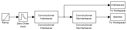
To build the model, gather and configure these blocks:
Ramp (Simulink), with default parameter settings.
Zero-Order Hold (Simulink), with default parameter settings.
Convolutional Interleaver, with these updates to parameter settings:
Set Rows of shift registers to
3.Set Initial conditions to
[-1 -2
                                        -3]'
.
Convolutional Deinterleaver, with these updates to parameter settings:
Set Rows of shift registers to
3.Set Initial conditions to
[-1 -2
                                        -3]'
.
Two copies of To Workspace (Simulink), with these updates to parameter settings:
Set Variable name to
interleavedandrestored, respectively, in the two copies of this block.Set Save format to
Arrayin each of the two copies of this block.
Tip
Select the To Workspace block from the DSP System Toolbox / Sinks sublibrary. For more information, see To Workspace Block Configuration for Communications System Simulations.
On the Simulation tab, in the
Simulate section, set Stop
time to 20. The
Simulate section appears on multiple tabs. Run
the simulation and execute the following command:
comparison = [[0:20]', interleaved, restored]

comparison =

     0     0    -1
     1    -2    -2
     2    -3    -3
     3     3    -1
     4    -2    -2
     5    -3    -3
     6     6    -1
     7     1    -2
     8    -3    -3
     9     9    -1
    10     4    -2
    11    -3    -3
    12    12     0
    13     7     1
    14     2     2
    15    15     3
    16    10     4
    17     5     5
    18    18     6
    19    13     7
    20     8     8
In this output, the first column contains the original symbol sequence. The second column contains the interleaved sequence, while the third column contains the restored sequence.
The negative numbers in the interleaved and restored sequences come from the interleaving blocks' initial conditions, not from the original data. The first of the original symbols appears in the restored sequence only after a delay of 12 symbols. The delay of the interleaver-deinterleaver combination is the product of the number of shift registers (3) and the maximum delay among all shift registers (4).
For a similar example that also indicates the contents of the shift registers at each step of the process, see Convolutional Interleaving and Deinterleaving Using a Sequence of Consecutive Integers in MATLAB.
Selected Bibliography for Interleaving
[1] Berlekamp, E.R., and P. Tong, “Improved Interleavers for Algebraic Block Codes,” U. S. Patent 4559625, Dec. 17, 1985.
[2] Clark, George C., and J. Bibb Cain. Error-Correction Coding for Digital Communications. Applications of Communications Theory. New York: Plenum Press, 1981.
[3] Forney, G. D. Jr., “Burst-Correcting Codes for the Classic Bursty Channel,” IEEE Transactions on Communications, vol. COM-19, October 1971, pp. 772-781.
[4] Heegard, Chris and Stephen B. Wicker. Turbo Coding. Boston: Kluwer Academic Publishers, 1999.
[5] Ramsey, J. L, “Realization of Optimum Interleavers,” IEEE Transactions on Information Theory, IT-16 (3), May 1970, pp. 338-345.
[6] Takeshita, O. Y. and D. J. Costello, Jr., “New Classes Of Algebraic Interleavers for Turbo-Codes,” Proc. 1998 IEEE International Symposium on Information Theory, Boston, Aug. 16–21, 1998. pp. 419.