dsp.IIRDecimator
R2026bDescription
The dsp.IIRDecimator
System object™ performs polyphase IIR decimation of the input signal. The object implements a
polyphase structure where each branch contains one or more allpass filter sections. The object
determines the decimation factor based on the number of branches in the polyphase
structure.
To decimate the input signal by a factor of 2, use either the dsp.IIRHalfbandDecimator object or the dsp.IIRDecimator object.
The dsp.IIRHalfbandDecimator object is optimized specifically for decimation
by a factor of 2. To decimate the input signal by an arbitrary factor greater than or equal to
2, use the dsp.IIRDecimator object.
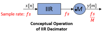
The object algorithm implements an IIR polyphase structure, an efficient equivalent of the combined system depicted in the diagram. For more details, see Algorithms.
To decimate the input signal:
Create the
dsp.IIRDecimatorobject and set its properties.Call the object with arguments, as if it were a function.
To learn more about how System objects work, see What Are System Objects?
Creation
Syntax
Description
iirdecim = dsp.IIRDecimator
iirdecim = dsp.IIRDecimator(Branches={Branch1,Branch2,...,BranchM})dsp.IIRDecimator(Branches={dsp.AllpassFilter(AllpassCoefficients=0.3),
dsp.AllpassFilter(AllpassCoefficients=0.5),
dsp.AllpassFilter(AllpassCoefficients=0.7)}) creates an IIR decimator with
three branches and a decimation factor of 3.
Properties
Usage
Syntax
Description
Input Arguments
Output Arguments
Object Functions
To use an object function, specify the
System object as the first input argument. For
example, to release system resources of a System object named obj, use
this syntax:
release(obj)
Examples
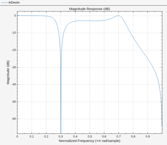
Create a polyphase IIR decimator with two allpass branches and visualize its magnitude and phase response using the filterAnalyzer function.
Define two allpass filter branches. The first branch is a first-order allpass filter and the second branch is a second-order allpass filter.
branches = {dsp.AllpassFilter(AllpassCoefficients=0.12), ...
    dsp.AllpassFilter(AllpassCoefficients=[0.36 0.58])};
Create the dsp.IIRDecimator System object using the allpass branches. The decimation factor equals the number of polyphase branches, which is two in this case.
iirDecim = dsp.IIRDecimator(Branches=branches)
iirDecim =
  dsp.IIRDecimator with properties:

    DecimationFactor: 2
            Branches: {[1×1 dsp.AllpassFilter]  [1×1 dsp.AllpassFilter]}
Visualize the frequency response of the IIR decimator using the filterAnalyzer function.
filterAnalyzer(iirDecim)
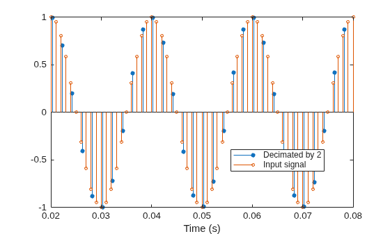
Create a polyphase IIR decimator, decimate a sinusoidal signal, and use the outputDelay function to align the decimated output with the original signal.
Define the allpass branches and create the dsp.IIRDecimator System object.
branches = {dsp.AllpassFilter(AllpassCoefficients=0.1550), ...
    dsp.AllpassFilter(AllpassCoefficients=[0.3726 0.6536])};
iirDecim = dsp.IIRDecimator(Branches=branches);
M = iirDecim.DecimationFactor;
Generate a sinusoidal signal with a frequency of 50 Hz and a sample rate of 1000 Hz using the dsp.SineWave System object. Use a long signal so that the IIR filter transient settles before the region of interest.
fs = 1000;
sineGen = dsp.SineWave(Frequency=50,SampleRate=fs, ...
    SamplesPerFrame=2000,PhaseOffset=pi/2);
x = sineGen();
Decimate the signal.
y = iirDecim(x);
Compute the output delay introduced by the IIR decimator using the outputDelay function. Use the delay to align the output with the input for comparison.
delay = outputDelay(iirDecim,FsIn=fs,Fc=50)
delay =
0.0017
Plot the input and decimated signals. Shift the output by the delay value so that the signals are aligned in time. Zoom into the steady-state region where the filter transient has settled. In the steady-state region, the decimated output samples align with the input signal after compensating for the group delay.
fsOut = fs/M;
nInput = (0:length(x)-1)/fs;
tOutput = (0:length(y)-1)/fsOut - delay;
stem(tOutput,y,"filled",MarkerSize=4); hold on;
stem(nInput,x,MarkerSize=3); hold off;
xlim([0.02 0.08])
xlabel("Time (s)")
legend("Decimated by " + M,"Input signal",Location="best");
Reduce the sample rate of an audio signal using a polyphase IIR decimator and play both the original and decimated signals.
Note: The audioDeviceWriter System object™ is not supported in MATLAB Online.
Define the allpass branches and create the dsp.IIRDecimator System object with a decimation factor of 2.
branches = {dsp.AllpassFilter(AllpassCoefficients=0.1550), ...
    dsp.AllpassFilter(AllpassCoefficients=[0.3726 0.6536])};
iirDecim = dsp.IIRDecimator(Branches=branches);
M = iirDecim.DecimationFactor;
Create a dsp.AudioFileReader object to read the audio signal.
afr = dsp.AudioFileReader("speech_dft_8kHz.wav");
fs = afr.SampleRate;
Create an audioDeviceWriter object to play the original audio signal at the original sample rate. Play the audio.
adw = audioDeviceWriter(fs);
while ~isDone(afr)
    audioIn = afr();
    adw(audioIn);
end
release(afr);
pause(0.5);
release(adw);
Create an audioDeviceWriter object to play the decimated audio signal at the reduced sample rate. Read, decimate, and play the audio.
adw = audioDeviceWriter(fs/M);
reset(afr);
while ~isDone(afr)
    audioIn = afr();
    audioOut = iirDecim(audioIn);
    adw(audioOut);
end
release(afr);
pause(0.5);
release(adw);
release(iirDecim);
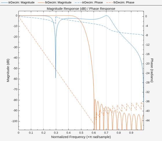
Create a polyphase IIR decimator and an FIR decimator with the same decimation factor. Compare their computational cost and frequency response.
Create an IIR decimator with a decimation factor of 2 using the dsp.IIRDecimator object.
branches = {dsp.AllpassFilter(AllpassCoefficients=0.1550), ...
    dsp.AllpassFilter(AllpassCoefficients=[0.3726 0.6536])};
iirDecim = dsp.IIRDecimator(Branches=branches);
Create an FIR decimator with the same decimation factor using the dsp.FIRDecimator object.
firDecim = dsp.FIRDecimator(2);
Compare the computational cost of both decimators using the cost function. The IIR decimator uses fewer multiplications and additions than the FIR decimator.
costIIR = cost(iirDecim)
costIIR = struct with fields:
                  NumCoefficients: 3
                        NumStates: 6
    MultiplicationsPerInputSample: 1.5000
          AdditionsPerInputSample: 3
costFIR = cost(firDecim)
costFIR = struct with fields:
                  NumCoefficients: 25
                        NumStates: 46
    MultiplicationsPerInputSample: 12.5000
          AdditionsPerInputSample: 12
Compare the frequency responses of both decimators using filterAnalyzer. The IIR polyphase decimator has significantly lower computational cost. However, it has a nonlinear phase response, unlike the FIR decimator which has linear phase.
filterAnalyzer(iirDecim,firDecim,...
    Analysis="magnitude",OverlayAnalysis="phase")
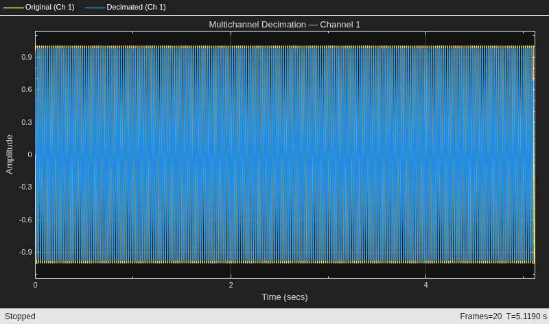
Create an IIR decimator and decimate a multichannel sinusoidal signal. Use a timescope object to visualize the original and decimated signals.
Define two allpass branches and create the dsp.IIRDecimator System object.
branches = {dsp.AllpassFilter(AllpassCoefficients=0.1550), ...
    dsp.AllpassFilter(AllpassCoefficients=[0.3726 0.6536])};
iirDecim = dsp.IIRDecimator(Branches=branches);
M = iirDecim.DecimationFactor;
Generate a 3-channel signal using the dsp.SineWave object. Each channel contains a sinusoid at a different frequency: 50, 100, and 150 Hz.
fs = 1000;
frameSize = 256;
sineGen = dsp.SineWave(Frequency=[50 100 150],SampleRate=fs, ...
    SamplesPerFrame=frameSize);
Compute the output delay introduced by the IIR decimator and use it to align the decimated output with the original signal on the time scope.
delay = outputDelay(iirDecim,FsIn=fs,Fc=50);
Create a timescope object with two input ports to display the original and decimated signals at their respective sample rates. Apply the delay as a time display offset to align the signals.
scope = timescope(NumInputPorts=2, ...
    SampleRate=[fs fs/M], ...
    TimeDisplayOffset=[0 -delay], ...
    TimeSpanSource="property",TimeSpan=0.05, ...
    ShowLegend=true, ...
    ChannelNames=["Original (Ch 1)","Decimated (Ch 1)"], ...
    Title="Multichannel Decimation — Channel 1");
Stream the signal through the IIR decimator and display the first channel on the time scope.
for k = 1:20
    x = sineGen();
    y = iirDecim(x);
    scope(x(:,1),y(:,1));
end
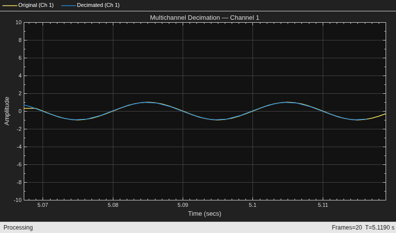
The decimated output aligns with the original signal after compensating for the group delay. The IIR decimator processes each column of the input independently, making it suitable for multichannel applications such as stereo audio or sensor array data.
Release the objects.
release(scope)
release(iirDecim)
Algorithms
Conceptually, the IIR decimation filter contains a lowpass IIR filter H(z) followed by a downsampler by M.
![Input x[n] at sample rate fs passing through polyphase IIR filter H(z), then downsampled by factor M to produce output y[m] at rate fs/M](iirdecimationfilter.png)
The IIR decimation filter uses a polyphase structure for efficient implementation. Each branch of the polyphase structure contains a cascade of one or more allpass filter sections.
To derive the polyphase structure, start with the transfer function of the IIR filter H(z). For a decimation factor of M, the transfer function of the IIR filter in polyphase form is
where:
M is the decimation factor that determines the number of polyphase branches.
z−k represents the delay associated with the k-th polyphase branch.
Ek(z) is a cascade of one or more allpass filter sections in the k-th polyphase branch. A single allpass filter section of order N has the following transfer function:
Because the numerator coefficients are the denominator coefficients in reverse order, |E(ejw)| = 1 for all frequencies (allpass property).
To express H(z) in polyphase form, replace it with its polyphase representation.
![Polyphase representation of H(z) with input x[n] split through delay elements into M IIR subfilters E0 through EM-1, summed, then downsampled by M to produce y[m]](iirdecimationfilter_polyphase.png)
The multirate noble identity for decimation is:

Applying the noble identity for decimation moves the downsampling operation before the filtering operation. This change enables you to filter the signal at a lower rate.
![Polyphase structure after applying noble identity, with downsampling by M moved before subfilters E0 through EM-1, outputs summed to produce y[m]](iir_decimator_applying_noble_identity.png)
You can replace the delays and the decimation factor at the input with a commutator switch. The switch starts on the first branch and moves in the counterclockwise direction. When the first input sample arrives, the commutator switch feeds this input to the first branch and the IIR decimator computes the first output value. As more input samples come in, the switch delivers one sample at a time to each branch alternately. The decimator generates output every time the switch returns to the first branch. This reduces the sampling rate of the input signal by a factor of M.
![Commutator switch feeding input x[n] at rate fs into polyphase subfilters E0 through EM-1, with accumulator producing output y[m] at rate fs/M](iirdecimationfilter_polyphase_ni.png)
References
[1] Renfors, Markku, and T. Saramaki, "Recursive N-th Band Digital Filters, Parts I and II," IEEE Trans. CAS, Vol. 34, pp. 24-51, Jan. 1987.
[2] Milic, Ljiljana. Multirate Filtering for Digital Signal Processing: MATLAB Applications. Information Science Reference, 2009.
[3] Harris, Fredric J. Multirate Signal Processing for Communication Systems. Prentice Hall, 2004.
Version History
Introduced in R2026b

