Logique décisionnelle
Stateflow permet de modéliser une logique de décision combinatoire et séquentielle dans un système de contrôle. Vous pouvez créer des structures logiques lisibles avec des diagrammes d’états, des diagrammes de flux et des tables de transition d’état.
Utilisez Stateflow pour créer des systèmes embarqués nécessitant une logique de contrôle, de supervision et modale. Stateflow modélise de manière naturelle des modes de fonctionnement faciles à intégrer dans un modèle Simulink®. Les outils de débuggage prédéfinis aident les développeurs à identifier et résoudre les problèmes de logique.
Rubriques
- Share Data with Simulink and the MATLAB Workspace (Stateflow)
Define data to share with Simulink models and the MATLAB® base workspace.
- Monitor State Activity Through Active State Data (Stateflow)
Automatically track which state is active during simulation.
- Access Bus Signals (Stateflow)
Define Stateflow buses for input, output, and local access to Simulink bus signals.
Informations connexes
Sélection d՚exemples

Model Battery Management System with Stateflow
Model a system to manage battery SOC, detect faults, and balance battery cells.

Model Fault-Tolerant Fuel Control System
Combine Stateflow and Simulink to model hybrid systems.

Detect and Isolate Faults in an Aircraft Elevator Control System
Design a fault detection, isolation, and recovery (FDIR) application for a pair of aircraft elevators controlled by redundant actuators.
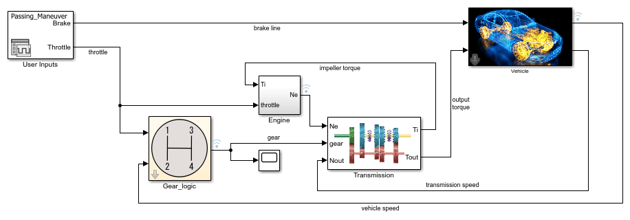
Implement an Automatic Transmission Gear System That Controls Transient Signals
Use debouncing logic to filter out transient signals that do not represent a true change of state.