Specify Initial Conditions for Bus Elements
Bus initialization specifies the bus element values that the software uses for the first
execution of a block that uses that bus. By default, the initial value for a bus element
is the ground value, represented by 0. Bus initialization involves
specifying nonzero initial conditions.
When you initialize buses, you can:
Specify initial conditions for signals that have different data types.
Apply a different initial condition for each element in a bus hierarchy.
Specify initial conditions for a subset of the elements in a bus hierarchy without specifying initial conditions for all the elements.
Use the same initial conditions for multiple blocks, signals, or models.
Bus initialization is a special form of signal initialization. For general information about initializing signals, see Initialize Signals and Discrete States. For information about initializing arrays of buses, see Initialize Arrays of Buses.
Blocks That Support Bus Initialization
These blocks support bus initialization:
Out Bus Element (when the block is in a conditionally executed context)
Outport (when the block is in a conditionally executed context)
To initialize a bus, use a block parameter such as Initial output or Initial conditions.
You cannot initialize a bus that has variable-size or frame-based signals, regardless of whether the block supports bus initialization.
Set Diagnostics to Support Bus Initialization
By default, new models support bus initialization. To make sure that bus
initialization is enabled, before you start a simulation, check that the
Underspecified initialization
detection configuration parameter is set to
Simplified (default).
On the Modeling tab, click Model Settings.
In the Configuration Parameters dialog box, search for the configuration parameter by name. Alternatively, find the configuration parameter by navigating to the Diagnostics > Data Validity pane, pausing on the ellipsis at the bottom of the pane, and expanding the Advanced parameters section.
Check that Underspecified initialization detection is set to
Simplified.Click OK.
Explore Types of Initial Condition Structures
To initialize a bus, you must create a partial or full initial condition structure that represents the initial values for the elements in the bus hierarchy.
A partial initial condition structure provides initial values for a subset of the elements of a bus. If you use a partial initial condition structure, during simulation, the software creates a full initial condition structure to represent all the bus elements. When you use partial structures, the software initializes unspecified signals implicitly. The software assigns the respective ground value to each element for which the partial initial condition structure does not explicitly assign a value.
A full initial condition structure provides an initial value for each element of a bus. The initial condition structure mirrors the bus hierarchy and reflects the attributes of the bus elements.
Specifying partial structures can be useful while you iteratively develop a model. Partial structures let you focus on a subset of the elements in a bus.
Specifying full structures can be useful for generating more readable code and supporting modeling styles that explicitly initialize all signals.
Requirements for Initial Condition Structures
The fields that you specify in an initial condition structure must match these data attributes of each bus element exactly:
Name
Dimension
Complexity
For example, suppose you define a bus element to be a real [2x2]
double array. In the initial condition structure, you must
define the corresponding initial value as a real [2x2] double
array.
Explicitly specify fields in the initial condition structure for every bus element
that has an enumerated (enum) data type.
If a bus element uses a data type other than double, you can
use different techniques to control the data types of the fields of initial
condition structures. The technique that you choose can influence the efficiency and
readability of the generated code. For more information, see Control Data Types of Initial Condition Structure Fields.
The value of an initial condition structure must lie within the design minimum and maximum range of the corresponding bus element. The software performs this range checking when you do an update diagram or simulate the model.
When you create a partial initial condition structure:
Include only fields that are in the bus.
Omit one or more fields that are in the bus.
Make the field in the initial condition structure correspond to the nesting level of the bus element.
Within the same nesting level in both the structure and the bus, optionally specify the structure fields in a different order than the bus elements.
Create Initial Condition Structures
How you define an initial condition structure depends on your goals.
To create an initial condition structure from a
Simulink.Busobject interactively, use the Type Editor.In the docked Type Editor, right-click the
Simulink.Busobject. Then, select Create MATLAB Structure.In the standalone Type Editor, select the
Simulink.Busobject. Then, in the Type Editor toolstrip, click MATLAB Structure.
To create an initial condition structure from a bus or
Simulink.Busobject programmatically, use theSimulink.Bus.createMATLABStructfunction.
The Type Editor and Simulink.Bus.createMATLABStruct
function streamline the creation of a full initial condition structure with the same
hierarchy, names, and data attributes as a bus. For the elements to which you do not
assign values, the structure specifies ground values.
You can also create the structure manually. For more information, see Structure Arrays.
Specify Initial Condition Structures
For a block that supports bus initialization, you can specify an initial condition structure using one of the approaches in this table.
| Approach | Example |
|---|---|
MATLAB® structure that explicitly defines the initial conditions for the bus | Set the initial condition to
For
more information, see |
MATLAB variable that represents an initial condition structure with the appropriate values | Set the initial condition to K = struct('A',struct('A1',3),'B',4); |
| Suppose a bus object named P = Simulink.Parameter; P.DataType = "Bus: TopBus"; P.Value = Simulink.Bus.createMATLABStruct("TopBus"); P.Value.A.A1 = 3; P.Value.B = 4; For more information, see Organize Related Block Parameter Definitions in Structures. |
When you define an initial condition structure with a MATLAB variable or Simulink.Parameter object, you
can:
Reuse the initial condition structure for multiple blocks.
Use the initial condition structure as a tunable parameter in the generated code.
When you specify the initial condition structure directly, you cannot reuse the structure and you limit the tunability of the structure.
You can also specify an initial condition structure with a Simulink.Signal object.
Inspect and Modify Bus Initialization
This example shows how to initialize the elements in a simple bus hierarchy.
Inspect Example Model
Open and compile the example model named BusInitialization. Compiling the model updates the line styles, which you can use to visually identify buses.
mdl = "BusInitialization";
open_system(mdl)
set_param(mdl,SimulationCommand="Update")
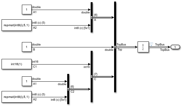
This model creates a bus hierarchy composed of three top-level elements named A, B, and C. The elements have these characteristics:
Ais a nested bus that contains signals namedA1andA2.Bis a signal.Cis a nested bus that contains a signal namedC1and a nested bus namedC2.C2contains the same elements as busA.
This table describes the relevant properties of the elements in the bus hierarchy.
Element | Data Type | Bus Virtuality | Dimensions | Complexity |
|---|---|---|---|---|
|
| Nonvirtual |
| - |
|
| Virtual |
| - |
|
| - |
|
|
|
| - |
|
|
|
| - |
|
|
|
| Virtual |
| - |
|
| - |
|
|
|
| Virtual |
| - |
|
| - |
|
|
|
| - |
|
|
To apply initial conditions to the bus, this example uses a Unit Delay block that receives the top-level bus.
In this example, K is a partial initial condition structure specified for the initial value of the Unit Delay block.
K
K = struct with fields:
    A: [1×1 struct]
K.A
ans = struct with fields:
    A1: 3
This structure initializes signal A1 in bus A to a value of 3.
Simulate the model.
sim(mdl);
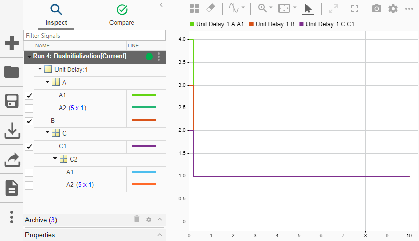
To view the simulation results, open the Simulation Data Inspector. Select both signals named A1: Top.A.A1 and Top.C.C2.A1.
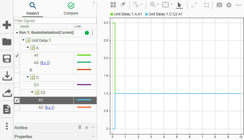
Structure K initializes Top.A.A1 to a value of 3. Meanwhile, Top.C.C2.A1 is not initialized by structure K. Instead, the software initializes this signal to the ground value 0.
Modify Bus Initialization
Update the structure to initialize only Top.C.C1. Specify a value of int16(4) or 4. You do not need to specify the data type explicitly.
K = struct("C",struct("C1",int16(4)))
K = struct with fields:
    C: [1×1 struct]
Simulate the model.
sim(mdl);
In the Simulation Data Inspector, select Top.C.C1 and clear Top.C.C2.A1.
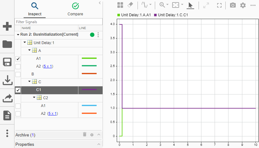
Structure K initializes Top.C.C1 to a value of 4. Meanwhile, Top.A.A1 is no longer initialized by structure K. Instead, the software initializes this signal to the ground value 0.
Update the structure to initialize Top.B and Top.A.A1. For bus elements at the same nesting level, such as Top.B and Top.A, the order of corresponding structure fields does not matter.
K = struct("B",3,"A",struct("A1",4))
K = struct with fields:
    B: 3
    A: [1×1 struct]
Simulate the model.
sim(mdl);
In the Simulation Data Inspector, select Top.B.
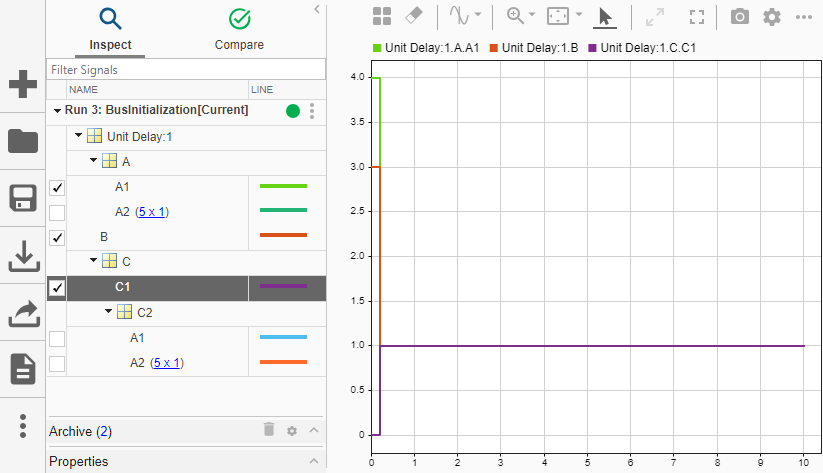
Structure K initializes Top.B and Top.A.A1 to values of 3 and 4, respectively. The software initializes Top.C.C1 and the other signals to the ground value 0.
To add an initial condition to a partial initial condition structure while keeping the existing initial conditions, use dot syntax. For example, keep the current initial conditions and initialize Top.C.C1 to a value of 2.
K.C.C1 = 2
K = struct with fields:
    B: 3
    A: [1×1 struct]
    C: [1×1 struct]
Simulate the model.
sim(mdl);
In the Simulation Data Inspector, Top.B, Top.A.A1, and Top.C.C1 have the initial values specified by structure K.
Identify Invalid Syntaxes
To help you identify valid and invalid syntaxes, this table provides examples of invalid syntaxes and the reason each of these syntaxes is invalid.
Invalid Syntax | Reason Syntax Is Invalid |
|---|---|
| Value dimension and complexity do not match. |
| You cannot use a scalar value to initialize a bus. |
| You cannot specify fields that are not in the bus. |
Check Structure Consistency with Bus
To identify blocks or Simulink.Signal objects that refer to
structure parameters that are not consistent in shape (hierarchy and names) or data
type with the associated bus, use the Model Advisor.
On the Modeling tab, click Model Advisor.
To select the default system, click OK.
Under By Task > Modeling Signals and Parameters using Buses, select Check structure parameter usage with bus signals.
Right-click Check structure parameter usage with bus signals. Then, click Run this check.
For more information, see Check structure parameter usage with bus signals.