Main Content

stereovslam

Feature-based visual simultaneous localization and mapping (vSLAM) and visual-inertial sensor fusion with stereo camera

Since R2024a

    Description

    Use the stereovslam object to perform visual simultaneous localization and mapping (vSLAM) with stereo camera data. To learn more about visual SLAM, see Implement Visual SLAM in MATLAB.

    The stereovslam object extracts Oriented FAST and Rotated BRIEF (ORB) features from incrementally read images, and then tracks those features to estimate camera poses, identify key frames, and reconstruct a 3-D environment. The vSLAM algorithm also searches for loop closures using the bag-of-features algorithm, and then optimizes the camera poses using pose graph optimization. You can enhance the accuracy and robustness of the SLAM by integrating this object with IMU data to perform visual-inertial sensor fusion.

    Creation

    Description

    vslam = stereovslam(intrinsics,baseline) creates a stereo visual SLAM object, vslam, using the rectified stereo camera intrinsic parameters intrinsics, and the baseline distance between the rectified left and right cameras.

    The object represents 3-D map points and camera poses in world coordinates, and assumes the camera pose of the first key frame is an identity rigidtform3d transform.

    Note

    The stereovslam object runs on multiple threads internally, which can delay the processing of an image frame added by using the addFrame function. Additionally, the object running on multiple threads means the current frame the object is processing can be different than the recently added frame.

    example

    vslam = stereovslam(reprojectionMatrix,imageSize) creates a stereo visual SLAM object vslam using the stereo camera reprojection matrix, reprojectionMatrix, and the image size, imageSize.

    vslam = stereovslam(___,imuParameters) performs stereo visual-inertial SLAM based on the specified imuParameters. Using this argument with IMU data, requires the Navigation Toolbox™

    vslam = stereovslam(___,PropertyName=Value) sets properties using one or more name-value arguments in addition to any combination of input arguments from previous syntaxes. For example, MaxNumPoints=850 sets the maximum number of ORB feature points to extract from each image to 850.

    Input Arguments

    expand all

    Rectified stereo camera intrinsic parameters, specified as a cameraIntrinsics object.

    This argument sets the Intrinsics property.

    Distance between the rectified left and right cameras, specified as a nonnegative scalar. Stereo vSLAM algorithms typically track the primary (or left) camera, in which case the baseline is greater than zero. A negative baseline value indicates a negative disparity range, and the vSLAM algorithm tracks the secondary (or right) camera instead.

    This argument sets the Baseline property.

    Reprojection matrix, specified as a 4-by-4 matrix of the form:

    where f and (cx, cy) are the focal length and principal point of rectified primary camera, respectively. b is the baseline of the virtual rectified stereo camera.

    You can obtain the reprojection matrix by using the rectifyStereoImages function.

    Image size produced by the camera, in pixels, specified as a two-element vector of the form [nrows ncols]. The elements nrows and ncols represent represents the number of rows and columns, respectively.

    IMU parameters, specified as a factorIMUParameters (Navigation Toolbox) object. The object contains the noise, bias, and sample rate information about the inertial measurement unit (IMU). Using this argument with IMU data, requires the Navigation Toolbox.

    Properties

    expand all

    Camera Parameters

    This property is read-only.

    Camera intrinsic parameters, stored as a cameraIntrinsics object.

    Use the intrinsics argument to set this property.

    Distance between the rectified left and right cameras, stored as a nonnegative scalar. Stereo vSLAM algorithms typically track the primary (or left) camera, in which case the baseline is greater than zero. A negative baseline value indicates a negative disparity range, and the vSLAM algorithm tracks the secondary (or right) camera instead.

    Use the baseline argument to set this property.

    This property is read-only.

    Disparity range, specified as a two-element vector of integers of the form [min max]. The elements specify the minimum and maximum disparity, respectively. The range must be within the width of the image, and the difference between the minimum and the maximum must be divisible by 16.

    Minimum value of uniqueness, specified as a nonnegative integer.

    The function marks the estimated disparity value K for a pixel as unreliable if:

    v < V×(1 + 0.01×UniquenessThreshold),

    where V is the sum of the absolute difference (SAD) corresponding to the disparity value K, and v is the smallest SAD value over the whole disparity range, excluding K, K–1, and K+1.

    Increasing the value of UniquenessThreshold results in the function marking disparity values for more pixels as unreliable. To turn off the uniqueness threshold, set this value to 0.

    Feature Extraction

    This property is read-only after object creation.

    Scale factor for image decomposition, stored as a scalar greater than 1. The scale factor is also referred to as the pyramid decimation ratio. Increasing the value of ScaleFactor reduces the number of pyramid levels, but reduce computation time. Decreasing this value (down to just over 1), increases the number of pyramid levels, which can improve tracking performance, at the cost of computation speed. The scale value at each level of decomposition is ScaleFactor(level-1), where level is any value in the range [0, Numlevels-1]. Given the input image of size M-by-N, the image size at each level of composition is Mlevel-by-Nlevel, where:

    Mlevel=MScaleFactor(level1)Nlevel=NScaleFactor(level1)

    This property is read-only after object creation.

    Number of decomposition levels, specified as an integer greater than or equal to 1. Increase this value to extract keypoints from the image at more levels of decomposition. Along with the ScaleFactor value, NumLevels controls the number of pyramid levels on which the object evaluates feature points.

    The image size at each decomposition level limits the number of levels at which you can extract keypoints. The image size at a level of decomposition must be at least 63-by-63 for keypoint detection. The maximum level of decomposition is calculated as

    levelmax = floor(log(min(M,N))log(63)log(ScaleFactor))+1

    If either the default value or the specified value of NumLevels is greater than levelmax, the object modifies NumLevels to levelmax and returns a warning.

    This property is read-only after object creation.

    Maximum number of ORB feature points uniformly extracted from each image, specified as a positive integer. Values are typically in the range of [800, 2000], depending on the resolution of the image. When the number of extracted features is less than the value of MaxNumPoints, then the object uses all feature points.

    Tracking

    This property is read-only after object creation.

    Key frame feature point range, stored as a two-element vector of positive integers in the form [lowerLimit upperLimit]. This property specifies the minimum and maximum numbers of tracked features points a frame must contain for the object to identify it as a key frame. The TrackFeatureRange and the SkipMaxFrames properties enable you to control the frequency at which frames in the tracking process become key frames.

    The success of tracking depends on the number of tracked points in the current frame, with one of these results:

    • Tracking is lost — The number of tracked feature points in the current frame is less than the lowerLimit set by the TrackFeatureRange argument. This indicates that the image does not contain enough features, or that the camera is moving too fast. To improve the tracking, you can increase the upperLimit value of the TrackFeatureRange property and decrease the SkipMaxFrames property to add key frames more frequently.

    • Tracking is successful — The object identifies the current frame as a key frame. The number of tracked feature points in the current frame is in the range set by TrackFeatureRange.

    • Tracking adds key frames too frequently — The number of tracked feature points in the current frame is greater than the upperLimit set by the TrackFeatureRange property. This indicates that the camera is moving very slowly, which produces an unnecessary number of key frames. To improve the tracking, you can reduce the frequency of adding key frames by increasing the value of the SkipMaxFrames property.

    For more details, see the addFrame object function.

    This property is read-only after object creation.

    Maximum number of skipped frames, stored as a positive integer. When the number of tracked features is consistently greater than the upperLimit set by the TrackFeatureRange property, use the SkipMaxFrames property to control the frequency at which the object adds new key frames. The object identifies the current frame as a key frame when the number of skipped frames since the most recently added key frame equals the value of SkipMaxFrames.

    This property is read-only after object creation.

    Minimum number of matched feature points between loop closure key frames, stored as a positive integer.

    This property is read-only after object creation.

    Custom bag of features for loop detection, specified as a bagOfFeaturesDBoW object. The bagOfFeaturesDBoW enables you to create a custom bag of words (BoW) from feature descriptors, alongside options to utilize a built-in vocabulary or load a custom one from a specified file.

    This property is read-only after object creation.

    Progress information display, specified as [], 1, 2, or 3. Paths to the location of log files, when they are created, is displayed on the command line.

    Verbose valueDisplay descriptionDisplay location
    [] or falseDisplay is turned off
    1 or trueStages of vSLAM executionCommand window
    2Stages of vSLAM execution, with details on how the frame is processed, such as the artifacts used to initialize the map. Log file in a temporary folder
    3Stages of vSLAM, artifacts used to initialize the map, poses and map points before and after bundle adjustment, and loop closure optimization data.Log file in a temporary folder

    IMU Fusion

    This property is read-only after object creation.

    IMU sensor transformation, specified as a rigidtform3d object. The transformation describes the rotation and translation of the camera in the coordinate system of the IMU sensor.

    This property is read-only after object creation.

    Number of estimated camera poses to trigger camera-IMU alignment, specified as an integer equal to or greater than 2. The process of aligning camera and IMU data is initiated after a specific number of camera poses have been estimated. This alignment serves two primary purposes: first, to estimate a scale factor that translates the up-to-scale results from a monocular camera into actual world units (meters), and second, to synchronize the IMU and camera frames, effectively eliminating the influence of gravity on accelerometer data. The timing for this alignment, determined by a threshold for the number of camera poses, is key to its success. A threshold set too low may not provide enough data for accurate calibration, while one set too high risks incorporating noise from measurement drift into the calibration. For a more in-depth understanding of this calibration technique, see the estimateGravityRotationAndPoseScale (Navigation Toolbox) function.

    This property is read-only after object creation.

    Subset of pose estimates, specified as a scalar in the range of (0,1]. This value specifies a fraction of the number of recent pose estimates, calculated as round(NumPosesThreshold*AlignmentFraction), for use in the camera-IMU alignment process. It effectively filters out initial, potentially noisy pose estimates, ensuring only the most relevant data contributes to the alignment for improved accuracy.

    Object Functions

    addFrameAdd pair of color and depth images to stereo visual SLAM object
    checkStatusCheck status of stereo visual SLAM object
    hasNewKeyFrameCheck if new key frame added in stereo visual SLAM object
    isDoneEnd-of-processing status for stereo visual SLAM object
    mapPointsBuild 3-D map of world points from stereo vSLAM object
    plotPlot 3-D map points and estimated camera trajectory in stereo visual SLAM
    posesAbsolute camera poses of stereo key frames
    resetReset stereo visual SLAM object

    Examples

    collapse all

    Perform stereo visual simultaneous localization and mapping (vSLAM) using the data from the UTIAS Long-Term Localization and Mapping Dataset provided by University of Toronto Institute for Aerospace Studies. You can download the data to a directory using a web browser, or by running this code:

    ftpObj = ftp("asrl3.utias.utoronto.ca");
    tempFolder = fullfile(tempdir);
    dataFolder = [tempFolder,'2020-vtr-dataset\UTIAS-In-The-Dark\'];
    zipFileName = [dataFolder,'run_000005.zip'];
    folderExists = exist(dataFolder,"dir");

    Create a folder in a temporary directory to save the downloaded file and extract its contents.

    if ~folderExists  
        mkdir(dataFolder) 
        disp("Downloading run_000005.zip (818 MB). This download can take a few minutes.") 
        mget(ftpObj,"/2020-vtr-dataset/UTIAS-In-The-Dark/run_000005.zip",tempFolder);
    
        disp("Extracting run_000005.zip (818 MB) ...") 
        unzip(zipFileName,dataFolder); 
    end

    Create two imageDatastore objects to store the stereo images.

    imgFolderLeft = [dataFolder,'\images\left\'];
    imgFolderRight = [dataFolder,'\images\right\'];
    imdsLeft = imageDatastore(imgFolderLeft);
    imdsRight = imageDatastore(imgFolderRight);

    Specify the intrinsic parameters and the baseline of the stereo camera, and use them to create a stereo visual SLAM object. The focal length, principal point, and image size is in pixels, and the baseline is in meters.

    focalLength = [387.777 387.777];  
    principalPoint = [257.446 197.718];  
    imageSize = [384 512];            
    intrinsics = cameraIntrinsics(focalLength,principalPoint,imageSize);
    baseline = 0.239965; 
    
    vslam = stereovslam(intrinsics,baseline,MaxNumPoints=600, ...
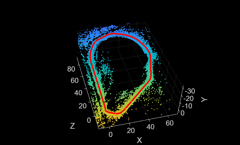
        TrackFeatureRange=[30 120],SkipMaxFrames=5);

    Process each pair of stereo images and visualize the camera poses and 3-D map points.

    for i = 1:numel(imdsLeft.Files)
        leftImage = readimage(imdsLeft,i);
        rightImage = readimage(imdsRight,i);
        addFrame(vslam,leftImage,rightImage);
    
        if hasNewKeyFrame(vslam)
            % Query 3-D map points and camera poses
            xyzPoints = mapPoints(vslam);
            [camPoses,viewIds] = poses(vslam);
    
            % Display 3-D map points and camera trajectory
            plot(vslam);
        end
    
        % Get current status of system
        status = checkStatus(vslam);
        
        % Stop adding frames when tracking is lost
        if status == uint8(0)
            break
        end
    end 

    Once all the frames have been processed, reset the system.

    while ~isDone(vslam)
        plot(vslam)
    end

    Figure contains an axes object. The axes object with xlabel X, ylabel Y contains 12 objects of type line, text, patch, scatter. This object represents Camera trajectory.

    reset(vslam)

    Tips

    • The stereovslam object:

      • Does not account for lens distortion. You can undistort the images by using the undistortImage function before adding images.

      • Assumes images have been rectified. You can rectify undistorted stereo images by using the rectifyStereoImages function before adding images.

      • Runs on multiple threads internally, which can delay the processing of an image frame added by using the addFrame function. Additionally, the object running on multiple threads means the current frame the object is processing can be different than the most recently added frame.

    • The camera poses are the poses of the primary camera, which corresponds to the input image I1 added by the addFrame object function.

    • The object represents 3-D map points and camera poses in world coordinates. The object assumes the camera pose of the first key frame is an identity rigidtform3d transform.

    References

    [1] Mur-Artal and J. D. Tardós, "ORB-SLAM2: An Open-Source SLAM System for Monocular, Stereo, and RGB-D Cameras," in IEEE Transactions on Robotics, vol. 33, no. 5, pp. 1255-1262, Oct. 2017, doi: 10.1109/TRO.2017.2705103.

    Extended Capabilities

    expand all

    Version History

    Introduced in R2024a

    expand all