La traduction de cette page n'est pas à jour. Cliquez ici pour voir la dernière version en anglais.
Concepts de System Composer
System Composer™ allie les concepts de l’ingénierie système à ceux de Simulink®. Cette page définit ces concepts et leurs applications respectives afin de vous aider à comprendre comment ces domaines sont liés entre eux. Cette page permet également d’en savoir plus sur les concepts utiles et la manière dont ils s’appliquent au design de l’ingénierie système. Chaque section définit un concept, explique la manière dont le concept est utilisé dans System Composer, puis renvoie à de plus amples informations dans la documentation.
Créer des modèles pour décrire la structure des architectures systèmes et logicielles
Créer des comportements physiques pour les composants au moyen de Simscape
Étendre le langage de modélisation de l’architecture avec des profils et des stéréotypes
Représenter les alternatives de design au moyen de composants variants
Simplifier les architectures complexes en diagrammes plus simples en créant des vues filtrées
Simuler une architecture intégrée en implémentant les comportements des composants
Créer et simuler des diagrammes d’activité en vue d’une allocation aux composants
Selon l’objectif que vous poursuivez avec votre modélisation architecturale, consultez la section correspondante pour en savoir plus sur les concepts clés liés à cet objectif.
Créer des modèles pour décrire la structure des architectures systèmes et logicielles
Créez des modèles d’architecture dans System Composer afin de modéliser et de décrire votre système de systèmes.
| Terme | Définition | Application | Plus d’informations |
|---|---|---|---|
| Architecture | Une architecture System Composer représente un système de composants et la manière dont ils interagissent entre eux sur le plan structurel et comportemental. | Différents types d’architectures décrivent différents aspects des systèmes. Vous pouvez utiliser les vues pour visualiser un sous-ensemble de composants dans une architecture. Vous pouvez définir des paramètres au niveau de l’architecture au moyen du Parameter Editor. | |
| Racine | Une racine se trouve au sommet d’une hiérarchie architecturale. Une architecture racine présente une limite définie par ses ports d’architecture qui entourent le système concerné. | L’architecture racine présente une limite système qui entoure votre modèle d’architecture. Vous pouvez ajouter des ports d’architecture qui définissent des interfaces au-delà de la limite. | |
| Modèle | Un modèle System Composer est un fichier qui contient des informations architecturales, telles que les composants, les ports, les connecteurs, les interfaces et les comportements. | Effectuez des opérations sur un modèle. Vous pouvez notamment extraire l’architecture de niveau racine, appliquer des profils, lier des dictionnaires de données d’interface ou générer des instances à partir de l’architecture du modèle. Un modèle System Composer est stocké sous la forme d’un fichier SLX. | Créer un modèle d’architecture avec des interfaces et des liens d’exigences |
| Composant | Un composant est une partie remplaçable d’un système qui remplit une fonction claire dans le contexte d’une architecture. Un composant définit un élément architectural, tel qu’une fonction, un autre système, du hardware, un logiciel ou toute autre entité conceptuelle. Un composant peut également se présenter sous la forme d’un sous-système ou d’une sous-fonction. | Représenté sous forme de bloc, un composant est une partie d’un modèle d’architecture qui peut être séparée en artefacts réutilisables. Transférez des informations d’un composant à l’autre par le biais des interfaces de port Interface Editor et des paramètres avec le Parameter Editor. | |
| Port | Un port est un nœud situé sur un composant ou une architecture qui représente un point d’interaction avec son environnement. Un port permet aux informations de circuler vers et depuis d’autres composants ou systèmes. | Les ports de composants sont des points d’interaction entre un composant et ses pairs. Les ports d’architecture sont des ports situés à la limite du système. Cette limite peut se trouver au sein d’un composant ou dans le modèle d’architecture global. L’architecture racine présente une limite définie par ses ports. | |
| Connecteur | Les connecteurs sont des lignes qui établissent une connexion entre les ports. Les connecteurs décrivent la manière dont les informations circulent entre les composants ou les architectures. | Un connecteur permet à deux composants d’interagir sans définir la nature de l’interaction. Définissez une interface sur un port pour déterminer la manière dont les composants interagissent entre eux. |
Créer des comportements physiques pour les composants au moyen de Simscape
Créez des modèles physiques dans System Composer au moyen de composants de sous-systèmes. Un composant de sous-système est un sous-système Simulink qui fait partie du modèle d’architecture System Composer parent. Les informations physiques peuvent dépasser les limites des composants du sous-système. Vous pouvez décrire les composants physiques avec des ports physiques, des connecteurs et des interfaces. Utilisez les blocs Simscape™ pour décrire le comportement de ces composants physiques.
| Terme | Définition | Application | Plus d’informations |
|---|---|---|---|
| Sous-système physique | Un sous-système physique est un sous-système Simulink doté de connexions Simscape. | Un sous-système physique avec des connexions Simscape utilise une approche de réseau physique adaptée à la simulation de systèmes avec des composants physiques réels et représente un modèle mathématique. | Implement Component Behavior Using Simscape |
| Port physique | Un port physique représente un port de connecteur de modélisation physique Simscape appelé Connection Port (Simscape). | Utilisez des ports physiques pour connecter des composants dans un modèle d’architecture ou pour activer des systèmes physiques dans un sous-système Simulink. | Define Physical Ports on Component |
| Connecteur physique | Un connecteur physique peut représenter une connexion de conservation non directionnelle d’un domaine physique spécifique. Les connecteurs peuvent également représenter des signaux physiques. | Utilisez des connecteurs physiques pour connecter les composants physiques qui représentent les fonctionnalités d’un système afin de le simuler mathématiquement. | Architecture Model with Simscape Behavior for a DC Motor |
| Interface physique | Une interface physique définit le type d’informations qui circulent par le biais d’un port physique. La même interface peut être attribuée à plusieurs ports. Une interface physique est une interface composite qui équivaut à un objet | Utilisez une interface physique pour regrouper des éléments physiques afin de décrire un modèle physique au moyen d’au moins un domaine physique. | Specify Physical Interfaces on Ports |
| Élément physique | Un élément physique décrit la décomposition d’une interface physique. Un élément physique correspond à un objet | Définissez le | Describe Component Behavior Using Simscape |
Décrire les spécifications du port au moyen d’interfaces
Définissez des interfaces afin de représenter le type d’informations qui circulent par le biais d’un port. Attribuez des interfaces aux ports au moyen de l’Interface Editor dans Dictionary View. Utilisez un bloc Adapter pour mettre en correspondance les interfaces sur un connecteur entre les ports.
Gérez les interfaces locales appartenant à un port au moyen de l’Interface Editor dans Port Interface View.
| Terme | Définition | Application | Plus d’informations |
|---|---|---|---|
| Dictionnaire de données | Un dictionnaire de données est un référentiel de données pertinentes pour votre modèle. La section Architectural Data d’un dictionnaire de données stocke les définitions partagées utilisées dans Simulink et les interfaces de modèle d’architecture, telles que les interfaces de port, les types de données et les constantes à l’échelle du système. Pour plus d’informations, consultez What Is a Data Dictionary?. | Vous pouvez enregistrer les interfaces locales d’un modèle System Composer dans la section Architectural Data d’un dictionnaire de données Simulink à l’aide de l’Interface Editor. Outre l’Interface Editor, vous pouvez également utiliser l’Architectural Data Editor pour gérer et modifier les interfaces et types de valeurs. | |
| Interface de données | Une interface de données définit le type d’informations qui circulent par le biais d’un port. La même interface peut être attribuée à plusieurs ports. Une interface de données peut être composite. Autrement dit, elle peut comprendre des éléments de données qui décrivent les propriétés d’un signal d’interface. | Les interfaces de données représentent les informations qui sont partagées par le biais d’un connecteur et qui entrent ou sortent d’un composant par le biais d’un port. Utilisez l’Interface Editor pour créer et gérer des interfaces de données et des éléments de données, puis stockez-les dans un dictionnaire de données afin de pouvoir les réutiliser entre les modèles. | |
| Élément de données | Un élément de données décrit une partie d’une interface, telle qu’un message de communication, un paramètre calculé ou mesuré, ou toute autre décomposition de cette interface. | Les interfaces de données sont décomposées en éléments de données pouvant correspondre aux broches ou fils d’un connecteur ou d’un faisceau, aux messages émis par le biais d’un bus et aux structures de données partagées entre les composants. | |
| Type de valeur | Un type de valeur peut être utilisé en guise d’interface de port afin de définir l’élément atomique de données qui transitent par ce port et qui possèdent un type de haut niveau, une dimension, une unité, une complexité, une valeur minimale, une valeur maximale et une description. | Vous pouvez également attribuer le type des éléments de données dans les interfaces de données à des types de valeurs. Ajoutez des types de valeurs aux dictionnaires de données à l’aide de l’Interface Editor afin de pouvoir réutiliser les types de valeurs en tant qu’interfaces ou éléments de données. | Create Value Types as Interfaces |
| Interface propriétaire | Une interface propriétaire est une interface locale qui appartient à un port spécifique et qui n’est pas partagée dans un dictionnaire de données ou le dictionnaire de modèles. | Créez une interface propriétaire pour représenter un type de valeur ou une interface de données locale appartenant à un port. | Define Owned Interfaces Local to Ports |
| Adaptateur | Un adaptateur connecte deux composants dotés d’interfaces de port incompatibles en les mappant entre les deux interfaces. Un adaptateur peut faire office de délai unitaire, de transition de débit ou de fusion. Vous pouvez également utiliser un adaptateur pour créer un bus. Utilisez le bloc Adapter pour implémenter un adaptateur. | Avec un adaptateur, dans la boîte de dialogue Interface Adapter, vous pouvez : créer et modifier des mappages entre les interfaces d’entrée et de sortie, appliquer une conversion d’interface |
Étendre le langage de modélisation de l’architecture avec des profils et des stéréotypes
Créez un profil dans Profile Editor et ajoutez-lui des stéréotypes avec des propriétés. Appliquez le stéréotype à un composant et définissez la valeur de la propriété dans Property Inspector.
| Terme | Définition | Application | Plus d’informations |
|---|---|---|---|
| Stéréotype | Les stéréotypes proposent un mécanisme permettant d’étendre les éléments linguistiques de base et d’ajouter des métadonnées propres à un domaine. | Appliquez des stéréotypes à des types d’éléments de base. Un élément peut avoir plusieurs stéréotypes. Les stéréotypes vous permettent de styliser différents éléments. Les stéréotypes proposent des éléments présentant un ensemble commun de propriétés, telles que la masse, le coût et la puissance. | |
| Propriété | Une propriété est un champ dans un stéréotype. Vous pouvez spécifier les valeurs de propriété pour chaque élément auquel le stéréotype est appliqué. | Utilisez les propriétés pour stocker les caractéristiques quantitatives, comme le poids ou la vitesse, associées à un élément de modèle. Les propriétés peuvent également être descriptives ou représenter un état. Vous pouvez afficher et modifier les propriétés de chaque élément du modèle d’architecture à l’aide du Property Inspector. Pour plus d’informations, consultez Use Property Inspector in System Composer. | |
| Profil | Un profil est un ensemble de stéréotypes. | Vous pouvez utiliser des profils pour créer un domaine de types d’éléments spécialisés. Créez des profils et appliquez-les à un modèle à l’aide de Profile Editor. Vous pouvez enregistrer les stéréotypes d’un projet dans un ou plusieurs profils. Lorsque vous enregistrez des profils, ceux-ci sont stockés dans des fichiers XML. |
Représenter les alternatives de design au moyen de composants variants
Créez des composants de variants et implémentez plusieurs alternatives ou variants de design, choisis sur la base de règles programmatiques. Ajoutez des choix de variants à un composant pour créer un composant variant. Le choix actif correspond au composant d’origine.
| Terme | Définition | Application | Plus d’informations |
|---|---|---|---|
| Variant | Un variant est l’un des nombreux choix structurels ou comportementaux d’un composant variant. | Utilisez des variants pour échanger rapidement différents designs architecturaux d’un composant tout en effectuant une analyse. | Créer des variants |
| Contrôle de variant | Un contrôle de variant est une chaîne qui contrôle le choix du variant actif. | Définissez le contrôle de variant de manière programmatique afin de déterminer quel variant est actif. | Set Variant Control Condition |
Utiliser l’analyse pour réaliser des études de compromis et valider les architectures par rapport aux contraintes
Créez une fonction d’analyse pour analyser la consommation électrique du modèle d’architecture RobotDesign.
function RobotDesign_1(instance,varargin)

if instance.isComponent() && ~isempty(instance.Components) ...
&& instance.hasValue('RobotProfile.ElectricalComponent.Power')
    sysComponent_power = 0;
    for child = instance.Components
        if child.hasValue('RobotProfile.ElectricalComponent.Power')
           comp_power = child.getValue('RobotProfile.ElectricalComponent.Power');
           sysComponent_power = sysComponent_power + comp_power;
           instance.setValue('RobotProfile.ElectricalComponent.Power', ...
           sysComponent_power);
        end
    end
end
Analysez le design du robot au moyen de la fonction d’analyse afin de déterminer la consommation électrique totale.
| Terme | Définition | Application | Plus d’informations |
|---|---|---|---|
| Analyse | L’analyse statique examine la structure du système afin d’évaluer quantitativement une architecture sur la base de certaines caractéristiques. L’analyse statique utilise une fonction d’analyse et les valeurs paramétriques des propriétés et des paramètres capturés dans le modèle du système. | Utilisez des analyses pour calculer la fiabilité globale, le déploiement de masse, les performances ou les caractéristiques thermiques d’un système, ou pour effectuer une analyse de taille, de poids et de puissance (SWaP) afin d’augmenter l’efficacité. | |
| Fonction d’analyse | Une fonction d’analyse est une fonction MATLAB® qui calcule les valeurs nécessaires à l’évaluation de l’architecture à l’aide des propriétés de chaque élément de l’instance du modèle et des paramètres propres à l’instance au niveau des composants et de l’architecture. | Utilisez une fonction d’analyse pour calculer le résultat d’une analyse. | |
| Modèle d’instance | Un modèle d’instance est un ensemble d’instances. | Vous pouvez mettre à jour un modèle d’instance en y intégrant les modifications apportées à un modèle. En revanche, le modèle d’instance ne sera pas mis à jour avec les modifications apportées aux variants actifs ou aux références de modèle. À des fins d’analyse, vous pouvez utiliser un modèle d’instance, enregistré dans un fichier | Run Analysis Function |
| Instance | Une instance est une occurrence d’un élément de modèle d’architecture à un moment donné. | Une instance fige le variant actif ou la référence de modèle du composant dans le modèle d’instance. | Create a Model Instance for Analysis |
Définir les relations qui existent entre les éléments de différents modèles d’architecture au moyen d’allocations
Dans l’Allocation Editor, allouez les composants entre deux modèles d’architecture en fonction d’une dépendance ou d’une relation directe.
| Terme | Définition | Application | Plus d’informations |
|---|---|---|---|
| Allocation | Une allocation permet d’établir une relation directe entre les éléments architecturaux (par exemple, composants, ports et connecteurs) d’un modèle et ceux d’un autre modèle. | L’allocation basée sur les ressources vous permet d’allouer des éléments architecturaux fonctionnels à des éléments architecturaux logiques et des éléments architecturaux logiques à des éléments architecturaux physiques. | |
| Scénario d’allocation | Un scénario d’allocation contient un ensemble d’allocations établies entre un modèle source et un modèle cible. | Effectuez des allocations entre les éléments du modèle dans un scénario d’allocation. Le scénario d’allocation par défaut porte le nom de | Systems Engineering Approach for SoC Applications |
| Ensemble d’allocations | Un ensemble d’allocations se compose d’une ou de plusieurs allocations établies entre un modèle source et un modèle cible. | Créez un ensemble d’allocations avec des scénarios d’allocation dans Allocation Editor. Les ensembles d’allocation sont enregistrés sous forme de fichiers MLDATX. |
Simplifier les architectures complexes en diagrammes plus simples en créant des vues filtrées
Appliquez un filtre d’affichage pour générer un groupe d’éléments de composants qui seront affichés dans Architecture Views Gallery.
| Terme | Définition | Application | Plus d’informations |
|---|---|---|---|
| Vue | Une vue affiche un sous-ensemble personnalisable d’éléments dans un modèle. Les vues peuvent être filtrées sur la base de stéréotypes ou de noms de composants, de ports et d’interfaces, ainsi que du nom, du type ou des unités d’un élément d’interface. Créez des vues en ajoutant des éléments manuellement. Les vues permettent de simplifier le maniement d’architectures complexes en se concentrant sur certaines parties du design architectural. | Vous pouvez utiliser différents types de vues pour représenter le système. Passez d’un diagramme de composants à une hiérarchie de composants ou à une hiérarchie d’architecture. Pour les architectures logicielles, vous pouvez activer une vue de diagramme de classes. Un point de vue correspond à la perspective d’une partie prenante qui précise le contenu de la vue. | |
| Groupe d’éléments | Un groupe d’éléments est un ensemble de composants regroupés dans une vue. | Utilisez des groupes d’éléments pour remplir une vue de manière programmatique. | |
| Requêtes | Une requête est une spécification qui décrit certaines contraintes ou certains critères auxquels doivent satisfaire les éléments du modèle. | Utilisez des requêtes pour rechercher des éléments présentant certains critères de contrainte et pour filtrer les vues. | Find Elements in Model Using Queries |
| Diagramme de composants | Un diagramme de composants représente une vue contenant des composants, des ports et des connecteurs selon la structure du modèle. | Les diagrammes de composants vous permettent d’ajouter et de supprimer des composants de la vue de manière programmatique ou manuelle. | Inspecter les composants dans les vues architecture personnalisées |
| Diagramme de hiérarchie | Vous pouvez visualiser un diagramme de hiérarchie sous la forme d’une vue comportant des composants, des ports, des types de référence, des stéréotypes de composants et des propriétés de stéréotypes. | Les diagrammes de hiérarchie des composants affichent les composants sous la forme d’une arborescence dans laquelle les parents se trouvent au-dessus des enfants. Dans une vue hiérarchique des composants, chaque modèle référencé est représenté autant de fois qu’il est utilisé. Les diagrammes de hiérarchie architecturale affichent les types d’architecture uniques et leurs relations au moyen de connexions de composition. Dans une vue hiérarchique des composants, chaque modèle référencé n’est représenté qu’une fois. | Display Component Hierarchy and Architecture Hierarchy Using Views |
Simuler une architecture intégrée en implémentant les comportements des composants
Utilisez un composant de référence pour décomposer et réutiliser les composants architecturaux et modéliser les comportements de modèle Simulink. Utilisez un composant de sous-système ou un diagramme d’état pour implémenter les comportements Simulink et Stateflow®.
| Terme | Définition | Application | Plus d’informations |
|---|---|---|---|
| Composant de référence | Un composant de référence est un composant dont la définition est un modèle d’architecture distinct, un modèle de comportement Simulink ou un comportement de sous-système Simulink. Un composant de référence représente une hiérarchie logique d’autres compositions. | Vous pouvez synchroniser et réutiliser les composants de référence sous forme de blocs Reference Component. Les références de modèle sont des modèles Simulink. Les composants FMU sont des composants liés à des fichiers FMU (Functional Mockup Unit). Les références de sous-système sont des sous-systèmes Simulink. Les références d’architecture sont des modèles d’architecture ou des sous-systèmes System Composer. | |
| Paramètre | Un paramètre est une valeur propre à une instance d’un type de valeur. | Les paramètres sont disponibles pour les architectures et les composants qui font partie du modèle d’architecture. Des paramètres sont également disponibles pour les composants liés à des références de modèle, de sous-système ou d’architecture qui spécifient des arguments de modèle. Vous pouvez spécifier des valeurs indépendantes pour un paramètre sur chaque composant. | |
| Composant de sous-système | Un composant de sous-système est un sous-système Simulink qui fait partie du modèle d’architecture System Composer parent. | Ajoutez le comportement du sous-système Simulink à un composant pour créer un composant de sous-système dans System Composer. Vous ne pouvez pas synchroniser et réutiliser les composants du sous-système en tant que blocs Reference Component. En effet, le composant fait partie du modèle parent. | |
| Statechart | Un diagramme statechart illustre le comportement d’un composant en fonction de son état tout au long de son cycle de vie et les événements pouvant déclencher une transition entre deux états. | Ajoutez un comportement de diagramme Stateflow pour décrire un composant au moyen de machines à états. Vous ne pouvez pas synchroniser et réutiliser les comportements de diagramme Stateflow en tant que blocs Reference Component. En effet, le composant fait partie du modèle parent. |
Gérer et vérifier les exigences afin de prouver que le système répond aux besoins des parties prenantes
La Requirements Perspective vous permet de créer, de gérer et d’allouer des exigences. Affichez les exigences d’un modèle d’architecture. Cette fonctionnalité nécessite une licence Requirements Toolbox™.
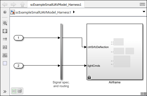
Utilisez Simulink Test™ pour créer un harnais de test pour un composant System Composer afin de valider les résultats de la simulation et de vérifier le design dans le Simulink Test Manager (Simulink Test). Cette fonctionnalité nécessite une licence SimulinkTest.
| Terme | Définition | Application | Plus d’informations |
|---|---|---|---|
| Exigences | Les exigences sont un ensemble d’instructions décrivant le comportement et les caractéristiques souhaités d’un système. Les exigences contribuent à garantir l’intégrité du design du système et doivent être réalisables, vérifiables, sans ambiguïté et cohérentes entre elles. Chaque niveau de design doit présenter des exigences adaptées. | Pour améliorer la traçabilité des exigences, liez les exigences système, fonctionnelles, client, de performances ou de design aux composants et aux ports. Liez les exigences entre elles afin de représenter les exigences dérivées ou allouées. Gérez les exigences à partir du Requirements Manager (Requirements Toolbox) sur un modèle d’architecture ou par le biais de vues personnalisées. Attribuez des cas de test aux exigences au moyen du Simulink Test Manager (Simulink Test) pour la vérification et la validation. | |
| Ensemble d’exigences | Un ensemble d’exigences est un regroupement d’exigences. Vous pouvez structurer les exigences de manière hiérarchique et les lier à des composants ou à des ports. | Utilisez le Requirements Editor (Requirements Toolbox) pour modifier et affiner les exigences d’un ensemble d’exigences. Les ensembles d’exigences sont stockés dans des fichiers SLREQX. Vous pouvez créer un nouvel ensemble d’exigences et créer des exigences au moyen de Requirements Toolbox, ou encore importer des exigences à partir d’outils tiers supportés. | |
| Lien d’exigence | Un lien est un objet qui relie deux éléments de design sur la base d’un modèle. Un lien d’exigence est un lien dont la destination est une exigence. Vous pouvez lier des exigences à des composants ou des ports. | Affichez les liens dans System Composer au moyen de Requirements Manager (Requirements Toolbox). Sélectionnez une exigence dans le Requirements Browser afin de mettre en surbrillance le composant ou le port auquel l’exigence est attribuée. Les liens sont stockés en externe dans des fichiers SLMX. | |
| Harnais de test | Un harnais de test est un modèle qui isole le composant à tester, avec des entrées, des sorties et des blocs de vérification configurés pour les scénarios de test. Vous pouvez créer un harnais de test pour un composant de modèle ou pour un modèle complet. Un harnais de test met à votre disposition un environnement de test distinct pour un modèle ou un composant de modèle. | Créez un harnais de test pour un composant System Composer afin de valider les résultats de la simulation et de vérifier le design. Pour modifier les interfaces pendant que vous testez le comportement d’un composant dans un harnais de test, utilisez l’Interface Editor. |
|
Spécifier les contraintes opérationnelles entre les composants au moyen de diagrammes de séquence exécutables
Créez un diagramme de séquence dans l’Architecture Views Gallery pour décrire les interactions du système.
| Terme | Définition | Application | Plus d’informations |
|---|---|---|---|
| Interaction | Une interaction spécifie la manière dont chaque partie d’un système doit interagir sous la forme d’une séquence d’échanges de messages. | Utilisez les interactions pour décrire les comportements opérationnels du système. | Describe System Behavior Using Sequence Diagrams |
| Diagramme de séquence | Un diagramme de séquence est une représentation visuelle d’une interaction. | Utilisez des diagrammes de séquence pour spécifier visuellement la manière dont chaque partie d’un système doit interagir. | Describe System Behavior Using Sequence Diagrams |
| Ligne de vie | Une ligne de vie représente une instance d’un composant en tant que participant à une interaction. | Une ligne de vie correspond à un composant dans une architecture. | Describe Interactions with Lifelines and Messages |
| Message | Un message représente une communication entre deux lignes de vie. Les messages arborent des étiquettes qui précisent les conditions dans lesquelles ils sont susceptibles de se produire. | Une étiquette de message comporte un déclencheur, une condition facultative et une contrainte facultative. Le déclencheur représente l’événement identifiant ce message, la condition représente une condition supplémentaire permettant de déterminer si le message se produit, et la contrainte est une expression qui doit se vérifier pour que ce message apparaisse. | Describe Interactions with Lifelines and Messages |
| Porte | Une porte représente la racine d’une hiérarchie architecturale. | Une porte vous permet de décrire l’échange de messages entre l’architecture et son environnement. | Describe Interactions with Lifelines and Messages |
| Annotation | Une annotation décrit les éléments d’un diagramme de séquence. | Utilisez des annotations pour mettre à disposition des explications détaillées concernant les éléments ou les workflows représentés par les diagrammes de séquence. | Annotate Sequence Diagrams with Annotations |
| Fragment | Un fragment englobe un groupe de lignes de vie et de messages au sein d’une interaction afin de permettre la spécification de modèles d’interaction plus complexes. | Un fragment définit le type de logique d’ordonnancement, comme les boucles et les alternatives. Les fragments peuvent présenter un ou plusieurs opérandes. | Model Complex Interactions with Fragments and Operands |
| Opérande | Un opérande est une région dans un fragment ou un groupe de messages. La condition d’un opérande spécifie si les messages contenus dans l’opérande sont exécutés. | La condition d’un opérande peut spécifier des contraintes sur le signal d’entrée d’une ligne de vie sous la forme d’une expression booléenne MATLAB. | Model Complex Interactions with Fragments and Operands |
| Contrainte de durée | Une contrainte de durée définit une contrainte concernant le temps écoulé entre un début et une fin. | Utilisez les contraintes de durée pour exprimer explicitement une contrainte concernant la durée entre une occurrence de début et une occurrence de fin. | Specify Timing Constraints Between Message Events with Duration Constraints |
Créer et simuler des diagrammes d’activité en vue d’une allocation aux composants
Vous pouvez créer des diagrammes d’activité dans System Composer pour décrire les fonctionnalités de haut niveau du système. Utilisez des diagrammes d’activité pour décrire le comportement des systèmes comme une transformation des entrées en sorties par le biais d’actions qui traitent les flux de symboles. Vous pouvez également simuler et visualiser des diagrammes d’activité afin de valider le comportement du système.
Vous pouvez allouer des éléments d’un diagramme d’activité à des éléments d’un modèle d’architecture System Composer à l’aide de l’Allocation Editor afin de décrire plus en détail votre design architectural fonctionnel. Pour plus d’informations, consultez Design Architectures and Activity Diagram for Mobile Robot.
| Terme | Définition | Application | Plus d’informations |
|---|---|---|---|
| Diagramme d’activité | Un diagramme d’activité décrit le comportement d’un système en modélisant le flux de symboles entre les entrées et les sorties à travers une séquence contrôlée d’actions. Un diagramme d’activité contient des nœuds d’action reliés par des lignes de flux. | Utilisez des diagrammes d’activité pour conceptualiser un système, visualiser le flux fonctionnel des actions ou des décisions, et comprendre la manière dont les composants du système interagissent les uns avec les autres. | |
| Symbole | Les symboles sont des objets qui circulent dans le diagramme d’activité. Un symbole peut représenter des données telles que des structures et des entiers, ou simplement transmettre le contrôle. | Les symboles peuvent être de différents types :
| |
| Nœud d’action | Un nœud d’action est un bloc de base essentiel d’un diagramme d’activité. Un nœud d’action représente une action à exécuter. Les nœuds d’action consomment des symboles d’entrée et produisent des symboles de sortie sur les pins. | Utilisez une fonction MATLAB ou un diagramme d’activité imbriqué pour décrire le comportement d’un nœud d’action. | |
| Nœud de contrôle | Un nœud de contrôle achemine un flux logique de symboles à travers le système. | Utilisez des nœuds de contrôle et des flux pour acheminer les symboles. Les nœuds de contrôle peuvent servir à initialiser, diviser, fusionner et terminer les flux de symboles. | Use Control Nodes to Manipulate Token Flows |
| Pin | Un pin sert de tampon pour les symboles d’objet et dirige les symboles vers ou depuis un nœud d’action. La direction du pin représente l’entrée ou la sortie. Vous pouvez connecter des pins par flux d’objets. | Utilisez des pins pour acheminer un symbole d’objet vers ou depuis un Action Node. Les pins servent également à stocker des symboles d’objet avant ou pendant l’exécution. Vous pouvez utiliser des pins uniquement pour les flux d’objets. | |
| Type | Un type définit le contenu d’un symbole qui circule à travers un pin. Un type présente une dimension, une unité, une complexité, une valeur minimale, une valeur maximale et une description. | Il existe trois types de symboles dans les diagrammes d’activité :
| |
| Nœud de paramètres | Un nœud de paramètres achemine les symboles vers ou depuis un diagramme d’activité imbriqué. Lorsqu’un pin est créé, un nœud de paramètres correspondant est créé à l’intérieur de l’activité imbriquée. | Utilisez le nœud de paramètres pour définir la manière dont les symboles entrent ou sortent d’une activité imbriquée. Il existe deux types de nœuds de paramètres, entrée et sortie. | |
| Flux | Un flux dans un diagramme d’activité connecte deux nœuds. Une ligne en pointillés représente un flux de contrôle. Une ligne continue représente un flux d’objets. | Les flux peuvent être de différents types :
| Simulate, Visualize, and Validate Activity Diagrams |
Créer, simuler et déployer des architectures logicielles
Concevez un modèle d’architecture logicielle, définissez l’ordre d’exécution des fonctions des composants, simulez le design au niveau de l’architecture et générez du code.
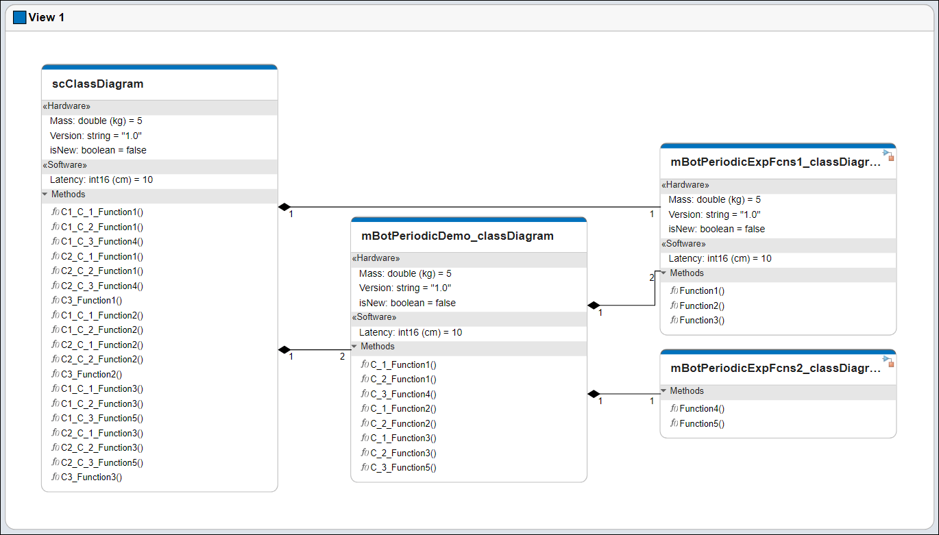
Affichez le diagramme de l’architecture logicielle sous la forme d’un diagramme de classes dans l’Architecture Views Gallery.
| Terme | Définition | Application | Plus d’informations |
|---|---|---|---|
| Architecture logicielle | Une architecture logicielle est une version spécialisée d’une architecture pour systèmes reposant sur des logiciels, comprenant la description des compositions logicielles, des fonctions des composants et de leur planification. | Les architectures logicielles System Composer permettent de créer des modèles d’architectures logicielles constitués de composants logiciels, de ports et d’interfaces. Concevez votre modèle d’architecture logicielle, définissez l’ordre d’exécution des fonctions de vos fonctions de composants, simulez votre design au niveau de l’architecture et générez du code. | |
| Composant logiciel | Un composant logiciel est une version spécialisée d’un composant pour les entités logicielles, y compris ses interfaces. | Implémentez une fonction d’exportation Simulink, sur la base du débit, ou un modèle JMAAB en tant que composant logiciel, simulez le modèle d’architecture logicielle et générez du code. | |
| Composition logicielle | Une composition logicielle est un diagramme des composants logiciels et des connecteurs qui représente une entité logicielle composite, telle qu’un module ou une application. | Encapsulez les fonctionnalités en agrégeant ou en imbriquant plusieurs composants logiciels ou compositions. | Model Software Architecture of Throttle Position Control System |
| Fonction | Une fonction est un point d’entrée où a lieu un transfert de contrôle du programme et qui peut être défini dans un composant logiciel. | Vous pouvez appliquer des stéréotypes aux fonctions dans les architectures logicielles, modifier les pas d’échantillonnage et spécifier la période de fonction à l’aide du Functions Editor. | Author and Extend Functions for Software Architectures |
| Élément de fonction | Un élément de fonction décrit les attributs d’une fonction dans une interface client-serveur. | Modifiez le prototype de fonction d’un élément de fonction afin de changer le nombre et les noms des entrées et sorties de la fonction. Modifiez les propriétés des éléments d’une fonction comme vous le feriez pour les propriétés des autres éléments de l’interface. Les types d’arguments de fonction peuvent inclure des types intégrés, ainsi que des objets de bus. Vous pouvez spécifier des éléments de fonction pour supporter ce qui suit :
| systemcomposer.interface.FunctionElement |
| Argument de fonction | Un argument de fonction décrit les attributs d’un argument d’entrée ou de sortie dans un élément de fonction. | Vous pouvez définir les propriétés d’un argument de fonction dans Interface Editor comme vous le feriez pour d’autres types de valeurs : | systemcomposer.interface.FunctionArgument |
| Interface de service | Une interface de service définit l’interface de fonction entre les composants client et serveur. Chaque interface de service se compose d’un ou de plusieurs éléments de fonction. | Une fois que vous avez défini une interface de service dans Interface Editor, vous pouvez l’attribuer aux ports client et serveur à l’aide du Property Inspector. Vous pouvez également utiliser le Property Inspector pour attribuer des stéréotypes aux interfaces de service. | |
| Serveur | Un serveur est un composant qui définit et assure une fonction. | Un composant serveur désigne l’endroit où la fonction est définie. Vous pouvez implémenter le comportement d’une fonction dans un modèle de fonction d’exportation Simulink. | Service Interfaces Overview |
| Client | Un client est un composant qui envoie une requête au serveur. | Un composant client désigne l’endroit où la fonction est appelée. L’implémentation du comportement d’appel de fonction dépend de la synchronisation de l’exécution de la fonction. | Service Interfaces Overview |
| Diagramme de classe | Un diagramme de classe est une représentation graphique d’un modèle structurel statique qui affiche les types d’architecture uniques des composants logiciels, éventuellement accompagnés de méthodes et propriétés logicielles. | Les diagrammes de classe capturent une instance de chaque modèle référencé et présentent les relations qui les unissent. Une vue de diagramme de composants peut être représentée de manière facultative sous la forme d’un diagramme de classe pour un modèle d’architecture logicielle. | Class Diagram View of Software Architectures |
Voir aussi
Rubriques
- Composer et analyser des systèmes au moyen de modèles d’architecture
- Organize System Composer Files in Projects
- Simulate Mobile Robot with System Composer Workflow
- Modeling System Architecture of Small UAV